


sahib
Well-known member
Although the idea started a while ago in another thread I thought of starting a new one dedicated to this particular project.
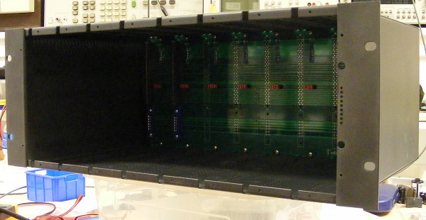
The idea is primarily a 4U, 8 channel, open platform base unit for a variety of use.
The module width is 2" and 250mm deep (less the edge connector height).
There are two separate backplanes. The connections between them are through eight 26 way ribbon cables. Fundamentally one 26 way ribbon per channel.
One backplane is for interfacing with the modules through the card edge connectors.
The other backplane is for interfacing with the outside world through XLR, TRS and DB25 connectors.
Only the inputs and outputs are available at the DB25 connectors in Tascam standard.
All the buses are terminated with box headers for cascading. So, the system can expand in 8 channel blocks.
The current rear panel is designed in 500 standard fashion but I am looking into other future alternatives.
I had only one pair of card edge connector samples but the rest will be in my hand by mid December. I will then complete the entire project.
In terms of the power supply I am keeping solid state and valve supplies separately. I have plenty of board options for the solid state. I will also be using my standard floorbox case. So not much work needed there. All I have to do is to design a new regulated HT.
I will be supplying the complete rack and/or individual components such as the backplanes and the rear panel, bear rack metalwork and module metalwork.
As it is an open platform I will make all the dimensions available.
Although I have not fitted yet rail voltage status LEDS (9 of them) are available on the RHS mounting bracket. There will also be two switches on the top and bottom to remotely control the floorbox power supplies so that you do not have to crawl behind the rack cabinet to turn them on/off.
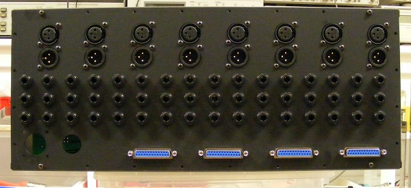
Rear panel. DB25 connectors are for INPUT 1 /1-8, INPUT 2 / 1-8, OUTPUT 1 /1-8 and OUTPUT 2 / 1-8.
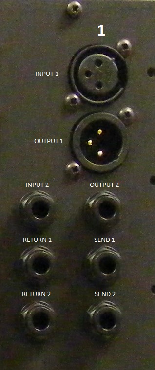
Typical channel arrangement.
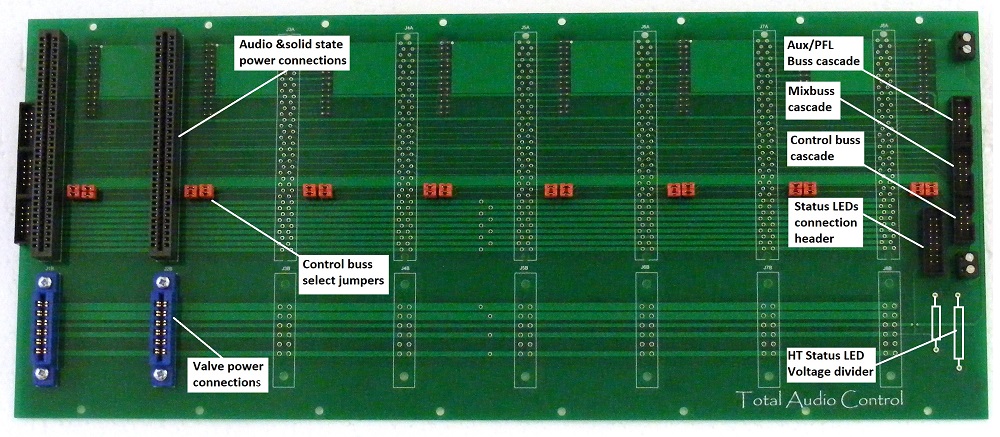
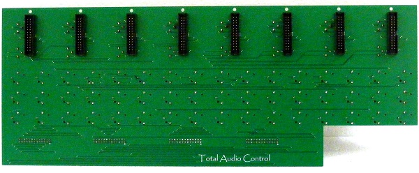
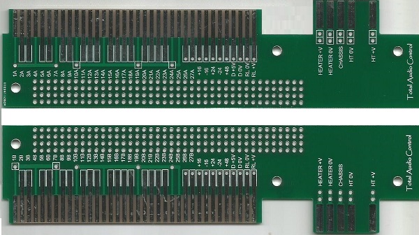
Card edge backplane (front view) for interfacing with the modules.
Notice the four control busses. The jumpers are for isolating a specific buss for a specific channel. Say you want to assign one of the buses for stereo linking of two compressors fitted in channel 1 and 2. Remove the respective jumper after channel 2. Now the buss only works between channel 1 and channel 2. You can break it up on the consecutive channels in the same fashion too.
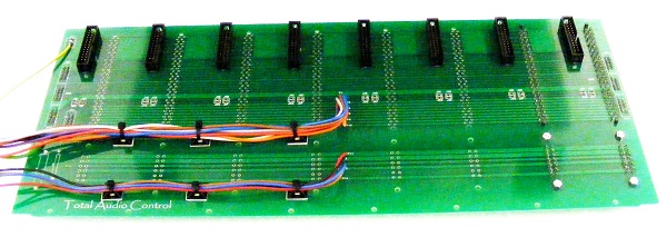
Card edge backplane rear view showing the box headers for connections to the XLR backplane, and the DC power connections.
The leads are soldered directly onto the board.
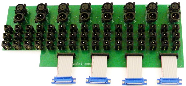
XLR backplane rear and front view, showing the connections to the external world and the box headers for connections to the card edge backplane.
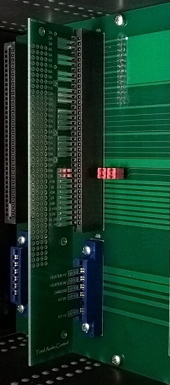
Card edge connections to the module. I have also designed an adapter card so that you can drop in any design you have in hand (provided that it fits) into the module metalwork and hard wire the audio and power connections straight onto the adapter card.
The idea is primarily a 4U, 8 channel, open platform base unit for a variety of use.
The module width is 2" and 250mm deep (less the edge connector height).
There are two separate backplanes. The connections between them are through eight 26 way ribbon cables. Fundamentally one 26 way ribbon per channel.
One backplane is for interfacing with the modules through the card edge connectors.
The other backplane is for interfacing with the outside world through XLR, TRS and DB25 connectors.
Only the inputs and outputs are available at the DB25 connectors in Tascam standard.
All the buses are terminated with box headers for cascading. So, the system can expand in 8 channel blocks.
The current rear panel is designed in 500 standard fashion but I am looking into other future alternatives.
I had only one pair of card edge connector samples but the rest will be in my hand by mid December. I will then complete the entire project.
In terms of the power supply I am keeping solid state and valve supplies separately. I have plenty of board options for the solid state. I will also be using my standard floorbox case. So not much work needed there. All I have to do is to design a new regulated HT.
I will be supplying the complete rack and/or individual components such as the backplanes and the rear panel, bear rack metalwork and module metalwork.
As it is an open platform I will make all the dimensions available.
Although I have not fitted yet rail voltage status LEDS (9 of them) are available on the RHS mounting bracket. There will also be two switches on the top and bottom to remotely control the floorbox power supplies so that you do not have to crawl behind the rack cabinet to turn them on/off.
Rear panel. DB25 connectors are for INPUT 1 /1-8, INPUT 2 / 1-8, OUTPUT 1 /1-8 and OUTPUT 2 / 1-8.
Typical channel arrangement.
Card edge backplane (front view) for interfacing with the modules.
Notice the four control busses. The jumpers are for isolating a specific buss for a specific channel. Say you want to assign one of the buses for stereo linking of two compressors fitted in channel 1 and 2. Remove the respective jumper after channel 2. Now the buss only works between channel 1 and channel 2. You can break it up on the consecutive channels in the same fashion too.
Card edge backplane rear view showing the box headers for connections to the XLR backplane, and the DC power connections.
The leads are soldered directly onto the board.
XLR backplane rear and front view, showing the connections to the external world and the box headers for connections to the card edge backplane.
Card edge connections to the module. I have also designed an adapter card so that you can drop in any design you have in hand (provided that it fits) into the module metalwork and hard wire the audio and power connections straight onto the adapter card.
")