The Idea

GroupDIY Audio Forum

Help Support GroupDIY Audio Forum:

This site may earn a commission from merchant affiliate links, including eBay, Amazon, and others.
Dear PRR,


    Thank you, as always. I understand now, but am a bit stumped as to the "floating" bit. if I use a transformer on the input of a HiFi amp, would that float it? Or would I need an output transformer instead/as well?

edit.  come to think of it, would a bridged amplifier be floating?


   KIndest regards,


      ANdyP
 
strangeandbouncy said:
Dear PRR,


    Thank you, as always. I understand now, but am a bit stumped as to the "floating" bit. if I use a transformer on the input of a HiFi amp, would that float it? Or would I need an output transformer instead/as well?

edit.  come to think of it, would a bridged amplifier be floating?


   KIndest regards,


      ANdyP
An imput xfmr would not "float the output, which would be more or less grounded (even if the power cord has no ground pin, there is still a not unsignificant capacitance to ground). As PRR said, the output must be floating if a full bridge rect is to be used. A half bridge would require a center-tap output xfmr. Or a bridged amplifier (although it wouldn't be floating).
 
Hi,


  Thanks again, i am still trying to get this. Why is a bridged amp not floating? speaker is connected to effectively +ve an -ve terminals, not to ground. . . .


  Does anyone have an idea as to how to float the output of a silicon poweramp, other than an expensive transformer? Perhaps I would be better off using a half bridge instead. Would this compromise the performance, other than giving a lower rectified control voltage? I am afterall not trying to protect a cutting head, or transmitter here, just some meaty squashiffication . . . !


    Kindest regards,


    ANdyP


strangeandbouncy said:
Hi,
Thanks again, i am still trying to get this. Why is a bridged amp not floating? speaker is connected to effectively +ve an -ve terminals, not to ground. . . .
The - terminal is usually connected to ground, sometimes not. Floating means that the output voltage is not referenced to ground in anyway. In a standard amp, the output is always referenced to ground, even a bridged amp.
Does anyone have an idea as to how to float the output of a silicon poweramp, other than an expensive transformer?
You can use expensive input transformers and very expensive low capacitance power transformers. :)
Perhaps I would be better off using a half bridge instead.
That would certainly be a much cost effective solution.
Would this compromise the performance, other than giving a lower rectified control voltage?
This would not even be an issue, since you can always specify the output transformer for the desired output voltage.
 
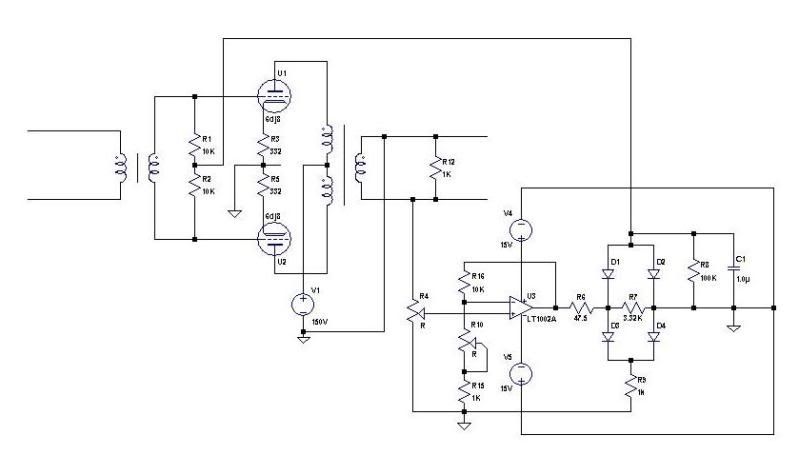
A schematic would be so much easer...don't you think?

More.jpg


That's a quick one I put together on the company time (I'm at work) but I would make an OPamp capable of swinging at least +/-70V and suddenly we are back to a complicated PSU.
 
There are some nice high voltage, high current op amps from TI.  I just ordered a couple for the compressor/limiter I'm working on.  I don't need -70V control voltage myself (more like -30V DC) but I think you may find something that will give you what you need.  Probably around $4 or $5 each so, not so bad really.  They can be run bipolar or single rail supply so you could AC couple and just snag the V+ from your H.T.
I'll be using two of them in a balanced configuration and forgoing the output transformer. 


Hi Winston, Hi Analag,


  Many thanks for your replies. Definately food for thought with both approaches. I was just wondering if there might be any use for a 100v line speaker transformer in reverse to step-up the voltage, and float the output? I am guessing that the impedance of the timing network is too low for this?


    Kindest regards,


      ANdyP

 
I used a chip amp and a 100volt line transformer/
Works pretty cool but is not quite as fast as the original. I think possibly an impedance issue.
I think i should have rated the amp a little higher aswell. I am getting 70volts on the grids though.

I tried a few tweaks but I think i am going to build the original control amp with tubes.

I am using 16 yes 16 matched 6BA6 tubes. I bought a box of 100 for $30 - good huh?

 
Hi Tardishead,


    Thanks for reply. I shall be starting with something similar. - and probably ending up with the real deal in the end! HOw big a chip-amp did you use btw?
    Bargain of the century if you ask me! 100 pcs for $30 .
. . .. 


    Kindest regards,


        AndyP
 
Winston O'Boogie said:
There are some nice high voltage, high current op amps from TI.  I just ordered a couple for the compressor/limiter I'm working on.  I don't need -70V control voltage myself (more like -30V DC) but I think you may find something that will give you what you need.  Probably around $4 or $5 each so, not so bad really.  They can be run bipolar or single rail supply so you could AC couple and just snag the V+ from your H.T.
I'll be using two of them in a balanced configuration and forgoing the output transformer.   

Wasn't there a circuit that MCI used, which sat a 5534 between something like + & - 36v power rails.  The op amp effectively swung between the power rails, in relation to the input signal, this enhancing it's output voltage range The output range was closer to a 70v swing than the normal 30v swing you would get from + & - 15v.
 
Hi Rob,

  I will look through my schemo's I am sure I have some MCI stuff - JH600 series.

    whereabouts in Sussex are you btw? I am in Haslemere.


  Kindest regards,


    ANdyP
 
strangeandbouncy said:
Hi Rob,

  I will look through my schemo's I am sure I have some MCI stuff - JH600 series.

    whereabouts in Sussex are you btw? I am in Haslemere.


   Kindest regards,


     ANdyP

Andy

I think I was shown that on a 500 diagram, but can't be sure.  Not sure if it is on all 500 series either.

I am in near Gatwick
 
analag said:
A schematic would be so much easer...don't you think?

More.jpg


That's a quick one I put together on the company time (I'm at work) but I would make an OPamp capable of swinging at least +/-70V and suddenly we are back to a complicated PSU.
Something wrong in this schematic...
Junction of D2, D4, V4 &V5 should not be tied to ground. Should be floating. And junction of R2 C1 should go to junction D3 D4.
 
abbey road d enfer said:
Something wrong in this schematic...
Junction of D2, D4, V4 &V5 should not be tied to ground. Should be floating. And junction of R2 C1 should go to junction D3 D4.
Wouldn't you be surprised to know it can work this way as well?
 
Hey Andy
I cannot remember exactky what chip amp it was - I think LM1875 which is rated 25 watts so should be easily enough but maybe I did not have the right 100 volt transformer. Its a big unit under my desk and not that easy to access at the moment but when I have time I will investigate into it further.
The original tailors the waveform a little aswell as far as I can remember. It has expansion or something?
 
analag said:
abbey road d enfer said:
Something wrong in this schematic...
Junction of D2, D4, V4 &V5 should not be tied to ground. Should be floating. And junction of R2 C1 should go to junction D3 D4.
Wouldn't you be surprised to know it can work this way as well?
I'm not surprised, it can work, but only single wave
 
Back
Top