the Poor Man 660 support thread

GroupDIY Audio Forum

Help Support GroupDIY Audio Forum:

This site may earn a commission from merchant affiliate links, including eBay, Amazon, and others.
Hi Mark,
#1 - I'm sure you're busy too but if you (or anyone with a GOOD working unit) could run some tests & sweeps, etc...
That would be cool. ;D
I'd love to see you're Frequency response Before & After compressing.
Same thing with individual test tones like = 100, 1k, 5k & 10k  (and be able to see the Harmonic Distortion of at least the 1k)

I actually thought about the Meter being the problem...
so a few days ago I disconnected the Meter & the Trimmer
then replaced them with a FIXED 64.5 ohm resistor just to see & nothing seemed to change.

(I measure Approx. 65 ohms across my meters with the Trimmer installed & Meter ZERO'd)

the distortion isn't drastic... it's just too noticeable & coloring even at moderate settings.
It sucks because it's so close.  :(


Hey kev,

My unit sounds ok to me but i would not mind do this respone thingy.


what is the procedure for running the test for distortion and signal response.


skal1
 
Cool.

It's not perfect but I'm sure the test would at least confirm what I'm measuring is in line with other builds.

If you have a way to:
  • Sweep the unit with & without compression (Try to dig into compression by about 10dB or so)

    Then test with individual test tones while compressing! = 100, 1k, 5k, 10k & 16k (we want to see if it compresses more starting around 1 or 2k on up) No compressor is perfect but it would be nice to see WHAT the PM660 does @ certain Frequencies & how close to "Flat" it is WHILE compressing.

    Harmonic Distortion - Run a test tone of 1k while compressing & (Doug mentioned lower Hz too... like 100Hz or lower )

With ALL these tests you have to increase your input GAIN & Adjust Threshold when "Compressing" to try & get the (non-Compressed) signals close for comparison.

NOTE: Many will say that "Sweeping" a comp is NOT a good way of testing because of the "Speed of the Comp or release time"
I do agree to some degree BUT I found that the "Individual Tones" showed the EXACT same roll-off from about 1k up as the "Sweep" did.

This increased compression on the higher frequencies MAY be normal for the PM660 design. This is would be nice to confirm or rule out.


NOTE #2 - I did run "Pink & White Noise" & they did look good & even - Both with & without Compressing

Pink noise is said to be the "Preferred" test.

Thank you.  :)

 
lewilson said:
My unit does not distort when compressing.  Maybe Your starving the  varimu tubes for current. I have 100 ohm trimmers and some old vu meters that seem to work well together.

I've been wondering how much difference meters make. There's a little in the pimping thread about this too.
There is a huge difference in sound and output with the meter simply connected or disconnected.  And it seems to be ok with my unit (not noticeable distortion) when there no resistance set for attack.  Otherwise if it's compressing, it's distorting heavily.

Is there a resistance that is ideal across the meter connection, so that the unit could be tested with a resistor in place of a meter?
Also, it there an easy way to tell if the varimu tubes are being starved for current?  Would the unit still work as designed if one of the tubes was pulled, and does it matter which tube?

and just to be clear - my voltages are all spot on, but tested with tubes in and 2 channels going.  Is this how everyone has tested?
Sorry - these are probably 'green-horn' questions, but maybe they will help others too.  And maybe some of the information has been covered, but this is getting to be a really big thread.
 
I've been wondering how much difference meters make. There's a little in the pimping thread about this too.
There is a huge difference in sound and output with the meter simply connected or disconnected.
Good morning  ;) Check the schemo and use Ohm's law with approximately 10ma in non GR mode  . Without meter you will have 22k in series so it's not a big deal to calculate voltage drop. As a matter of fact without meter unit will have less distortion with more GR. This unit can't work out of meter in parallel with 22k, unless you put something with similar resistance or simply bypass all that series resistance.
Is there a resistance that is ideal across the meter connection, so that the unit could be tested with a resistor in place of a meter?
I asked that several times before I pimped my unit with ma meter with almost zero resistance, So Resistance depends from meter sensitivity. People with VU recommend 5k trimmer.
Also, it there an easy way to tell if the varimu tubes are being starved for current?  Would the unit still work as designed if one of the tubes was pulled, and does it matter which tube?
I don't think that tubes are starving for current especially in GR mode. Unit will work without 1 tube but you will have double impedance in front of poor Edcor and probably loss of low freq's. It doesn't matter which tube, they are connected in parallel.
And yes,study  that schemo before you ask  ;)
 
excuse me for the daft question, but i scoured the thread and have yet to feel satisfied with an answer...

When wiring the gain/threshold switches, position 1 (0 ohms) of each deck is connected, right? and the the last position (15k) is connected to the transformer? I just have to make sure before i screw up these switches after soldering 48 resistors to each...

Thanks
Matt
 
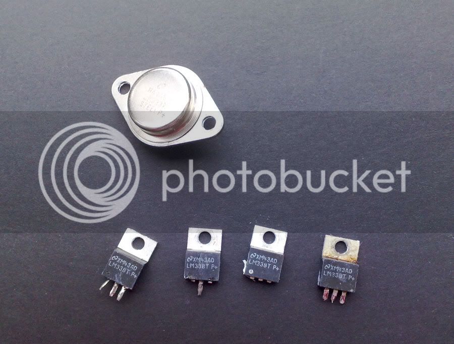
I think that I own this picture and short explanation about possible LM338 problems. Here is the pic wit fake LM338 I "killed" before I discovered that it's LM317 with fake print. It's possible that many of PM builders will have same situation , like overheating , not more than 2.5V at output and sucha ... So find the real one, ensure proper heatsink (not just a sheet of al) and be happy. Remember, LM is not human so if you can keep your finger on heatsink not more than 10 sec he is happy . If you burn your finger then thermal overload protection will  keep your LM alive but you must increase  a heatsink and air flow in the box.  Of course, your TX have to be ready for 2.4A (or2.6) per channel and don't hesitate to add some more capacitance in front of LM338. I ended with 2X10.000u for good smoothed DC.
fake-lm338.jpg
 
I've jsut tested my pm powersupply inkluding a pair of slow-start-heater pcb's - everything seems fine but the negative 17V rail. I can't adjust it to exactly -17V, either it's too high (-12/13V) or too low (under -20V) wich seems rather odd to me. Could it be a dodgy LM337? The trimmer seems to work fine if I measure the resistance while turning.

thanks
christoph
 
today I did some rewiring, I am still looking for a good place for the heater pcbs.

just powered the PSU for the first time, it seems to be just fine :)
this is a heavy project for me, I have only built small things before. but I won't quit !


Moby, I could only find those LM 338T's at Futurlec, mine has the same logo on it. could they be the wrong ones ?
and where did you get the right ones ?

thanks,

Jimi
 
connected the heater boards with the tubes, they are glowing. only the heatsink on the heater boards gets VERY hot, I do not know if this is good.. someone ?
 
elektrovolt said:
connected the heater boards with the tubes, they are glowing. only the heatsink on the heater boards gets VERY hot, I do not know if this is good.. someone ?

It's normal, but it's not optimal (we discussed this in detail in this thread many times already).

The heater regulator is dissipating the dropped voltage (about 9V to 6,3V) as heat and there is about 2.6A current going through it. A lot of work for a poor little piece of sand.
 
Moby said:
I think that I own this picture and short explanation about possible LM338 problems. Here is the pic wit fake LM338 I "killed" before I discovered that it's LM317 with fake print. It's possible that many of PM builders will have same situation , like overheating , not more than 2.5V at output and sucha ... So find the real one, ensure proper heatsink (not just a sheet of al) and be happy. Remember, LM is not human so if you can keep your finger on heatsink not more than 10 sec he is happy . If you burn your finger then thermal overload protection will  keep your LM alive but you must increase  a heatsink and air flow in the box.  Of course, your TX have to be ready for 2.4A (or2.6) per channel and don't hesitate to add some more capacitance in front of LM338. I ended with 2X10.000u for good smoothed DC.

Incredible , a part with code of another....

china attack is started ?

???  :eek:  ???
 
elektrovolt said:
indeed... I will try some other heatsinks too, maybe that will help.
Dont try it withouth heatsink. It will shut down after a while. And heatsink must be serious one, don't forget that it's passing 2.6A. Mine is working as a charm but I can hold my finger on it for a 10 sec. That's normal, don't worry chip is nor human being  ;)
 

Latest posts

Back
Top