This Works

GroupDIY Audio Forum

Help Support GroupDIY Audio Forum:

This site may earn a commission from merchant affiliate links, including eBay, Amazon, and others.
Maybe one of the guys can pull it up before I can. I will have to look through a lot of schematics.

analag
 
Hi Analag,
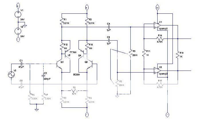
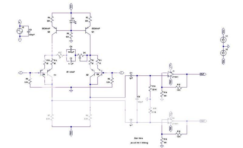
I don't know how this floated up to the surfac e, but it does look intriguing. I'd love to see the schematic too, as I need a superclean pre and Ithough I've looked plenty, I've never built one of your designs.
Hope you or somebody out there can find it.
Best
Kelly
 
Yes- second on the coolness. no hurry. I think I didn't explicitly say thanks on that last post so I'll throw this out there too. Thanks.
Sleeper
 
MicPre.jpg


I think I will have to do this one from memory, with some changes as well.
R5 is a pot, preferably reverse tapered. It is a trim control. R8/R9 would be a rotory switch or dual pot which is used for gain. Opamp would be an OPA2604 for low noise, FET input and high voltage (+/-24V) rail.
Feel free to disect.
icon_wink.gif


analag
 
Interesting, thanks.

The front-end is a composite diff pair as used in Rod Elliot's Project 66:

p66ra-f1.gif


In your schematic, current sources instead of R3/R4 (or single CS to a center-tapped R5) would increase CMRR at the expense of higher noise.

Setting gain through R8/R9 has the side effect of changing the LP rolloff. Why not vary R11 to change gain?

JDB.
[but how does it sound? Impossible to tell from the schematic, but it's indeed simple enough to build]
 
so, here it goes:

PreAmp7E0.jpg


kind of hard to read, because of photobucket´s limitations...

The other one you´ve posted in this page, looks closer to what you called "valley style"...
 
[quote author="rafafredd"]so, here it goes:

PreAmp7E0.jpg


kind of hard to read, because of photobucket´s limitations...

The other one you´ve posted in this page, looks closer to what you called "valley style"...[/quote]
I haven't been following this thread but from a quick glance you could reduce common gain some more by connecting the ground side of the resistors at the minus inputs on both opamps to each other instead of to ground. The CM should be small due to using current sources on input devices, but less for no cost increase is usually OK, actually could use one less resistor.

JR
 

Latest posts

Back
Top