Voltage regulator Question ?

GroupDIY Audio Forum

Help Support GroupDIY Audio Forum:

This site may earn a commission from merchant affiliate links, including eBay, Amazon, and others.

PermO

Well-known member
Joined
Mar 16, 2011
Messages
815
Location
Hilversum, Netherlands
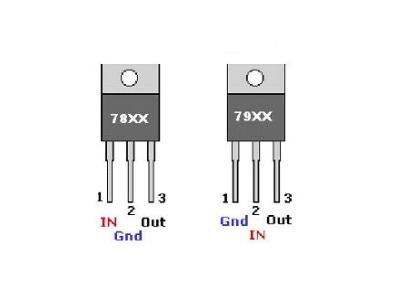
So I put together a small +18V -18V PSU on a piece of prefboard using a small 230V ~ 2 x 24V 31mA transformer, a pair of bridgerectifiers, a pair of 3300uF 50V caps and 7818 and 7918 as output regulators... fairly simple.

Though now I get +18V on one rail and -36V on the other rail ? ..there is +44V and -44V before the regulators.

I made a drawing tracing the prefboard to see if I made a mistake;
20240324_181109.jpg
I think this should be ok... (I might have drawn my capacitor polarity symbol wrong)

Is it possible I have coocked the regulator when soldering two small caps on it's legs right near it's housing ?

I have done this multiple times, this 7918 seems to be of a different brand though..

I don't get what's going on here :unsure:
 
Mind the pinout indeed, it's NOT identical between the 78xx and 79xx series.

9kRYN.jpg
 
I did mind the pinout, it is connected the right way.

Also, they are not attached to anything (yet) as I dont expect them to run hot with max 31mA load.

The 44V is with no load, not even a LED
 
Last edited:
I am not sure measuring the output voltages without a load is valid. It does not need to be a heavy load, just a 10K resistor maybe, but both regulators need a load in order to work properly.

Cheers

Ian
 
I usually take a transformer one step up to get enough voltage at the regulators, so 18V transformer for 15V output, in this case 18V output I looked for a 20V transformer but next in line was 24V so I went with that.

I took 5 LED's each with a 10K resistor to create a bit of a load, I put in on the working +18V output and voltage before the regulators dropped to 37V .... still seems a bit high.

Negative output still sits at -36V ... I did not put my load on that output as I did not expect that to solve the problem... it might blow 5 LED's...

I think I'll get the 18V transformer to get a 18V output in this case ...?
 
What if I apply a load resistor to ground before the regulator ?

I can try this on the working +18V side, see what value I need to drop the voltage below 30V, apply this on the other side as well and replace my 7918 ?

Worth a try I guess ?
 
Good question....

Because they are so easy in use, ~ ~ sit on one side and pins match the transformer pins, so you stick'm right on there.

But this does increase my output voltage... indeed
 
But this does increase my output voltage.

It shouldn't, you still have two diode drops between the input and output either way. Using a single bridge will have higher power dissipation in the bridge diodes, but if your intended use is really 30mA that should not be much concern.

44V is higher than I would expect from a 24V transformer though. Have you measured the unloaded AC voltage of the secondary? 24V RMS is 34V peak. A bridge rectifier will have two diode drops less than the peak voltage when the capacitors are fully charged, so 24V RMS AC should result in approximately 32V or 33V at the capacitors.
44V on the filter capacitors implies that the AC input is around 32V, or 30% higher than rated.
 
44V may be too much for the regulators.

The OnSemi datasheet I found, which is probably typical of modern generation linear regulators, listed -40V as absolute max. The usable range would be less than the absolute max, so probably in the range of -30V to -35V maximum input for the 7918 (and of course taking into account power dissipation).
 
I have used this same topology many times for small low power dual rail PSU's and never had any trouble with it.

I was also surprised to see 44V I expected it to be 30 something.

The 7818 is fine... the 7918 is a different (unknown to me) brand, and probably gave up.

Tomorrow I will disconnect the rectifiers and see what comes out of the secondary unloaded.
 
It seems pretty peculiar (notwithstanding the number of bridge rectifiers in use) that you would be getting 2 x 44V off the secondaries of a supposedly 2 x 24V transformer. With no (or low) load, I'd expect it to be a bit above the rated 24V per winding. Up to around 30V might be 'normal' for a no load condition. 44V is not what I'd expect.

That leads me to wonder whether the trafo you acquired is wound for 120V AC mains. That's about the only thing I can think of that might account for you getting 44V out of 24V windings.

That aside, I agree with the earlier poster who speculated that your 7918 chip is fried. The only surprising thing (given the 44V supply voltage) is that the 7818 is not also fried. ; )
 
Last edited:
It's a small PCB transformer and it's primary is rated 230VAC.

It is a single primary, two pins, only accepts 230VAC.
That being the case, my guess is that it's either mis-labelled or wildly off-spec.

That begs the question as to whether it's part of an entire batch of "2 x 24V" trafos that are putting out 2 x 44V. If so, even if you are able to return/exchange it, you may be no better off. But howsoever that may be, it's significantly out of spec IMO, and while that might not be your whole problem (e.g. if the 7918 is fried), it's likely the root of your problem, and you probably won't get to where you need to go without addressing it.
 
Last edited:
It seems pretty peculiar...that you would be getting 2 x 44V off the secondaries of a supposedly 2 x 24V transformer.

That is 44V peak, as noted in my previous post that would be around 32V RMS, or +30% of nominal rating. Transformers wound with small gauge wire (because the rated load is low) might have fairly large drop under load due to wire resistance, but 30% seems excessive even for a really cheap transformer.
Hard to say without a datasheet to reference.
 
The transformer is a Block VB 1,5/2/24

https://www.block.eu/en_EN/productversion/vb-15224

They do not mention outout voltage without load.


edit...

Interesting, I ordered two of these same transformers, so I took the one that was still in the box, put some wire clips on it to connect to mains and took a AC reading... weird ! 35V at both secundaries... seems perfectly normal.

Why do I get 44V DC ?
 
Last edited:
Why don't you do the same with the trafo in question to see what voltages you get?

BTW, where did you buy these transformers from? Directly from them? Just curious really cause I've never heard of them.
 
These transformers are very common in the EU, I got mine from Reichelt in Germany.

I'll have to desolder the rectifiers from the transformer to measure that, I'll come back to that later as I am now sanding and washing diecast enclosures to prep for powdercoating, these need to go out today.
 

Latest posts

Back
Top