Perf board primer please

GroupDIY Audio Forum

Help Support GroupDIY Audio Forum:

This site may earn a commission from merchant affiliate links, including eBay, Amazon, and others.

Family Hoof

Well-known member
Joined
Dec 17, 2004
Messages
406
Location
Brooklyn, New York, U.S.A.
I did some searching but didn't find much. When ordering perf board from a catalog (i.e. Digikey) there a many different specs and I'm having a hard time figuring out what to get.

Would anyone care to share some tips/guidelines for those of us who are less experienced?
 
Don't get the permali crap. Get the fiberboard, which is usually blue.

I like the ones that have the solder pads on them. More expensive, but better if you have a big circuit to do.
 
Would anyone care to share some tips/guidelines for those of us who are less experienced?
I won't start about solder fumes :wink: , but I thought there was some caution advised when drilling fiberboards. You won't be facing this much with those pre-drilled boards, but it might be good to know better not to drill that stuff (like for additional or larger holes) with your nose right above it. Small tiny :twisted: evil :twisted: particles attacking your lungs etc.

But: please tell if it's false alarm though, since I like the smell and would love to ... :roll: :oops: :shock:
 
Well,

If we're talking about perfboard or Veroboard as it's known over here (also matrix, stripboard etc) you have to specify which type you need. Firstly, there are two matrix sizes- 0.1" and 0.156" IIRC. I haven't seen the 0.156" stuff for years, and it's not much use for anything other than mounting larger non-IC components on. The advantage was that it would plug directly into 0.156" edge connectors...

The 0.1" is the most useful because you can fit transistors and IC's with the minimum of messing about and lead bending.

There are four types of board that I've used:

1. Plain "matrix" board without any copper strips.
2. Classic "veroboard" which has continuous copper strips running parallel across the board.
3. "Tri-pad" which is designed for maximum-density DIL IC mounting- ideal for building up boards of logic circuitry and other digital gubbins.
3. "Padboard" which has a small circular copper pad around each hole, but not electrically connected.

The plain matrix board can be useful to do a quasi-point to point circuit on- you basically bung your component leads through the holes, and solder their leads to eachother, and via small pieces of tinned copper wire. This can be a quick and easy way of knocking up an idea without too much work. Also, because of the lack of parallel copper tracks, your circuit layout can be very direct, although you have to use a lot of plastic sleeving to insulate the leads where they cross.

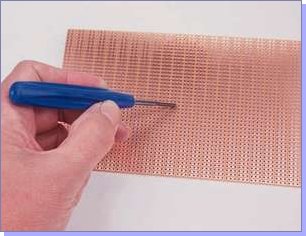
Classic "Veroboard" or "Stripboard" is my favourite. The idea is that you get a handy too like this:

011_02.jpg


...to cut the copper strips where you need breaks in continuity (or use a 4mm drill bit :wink: ) With a bit of careful forward planning you can create very elegant board layouts very quickly. Here's a handy layout sheet to help with planning:

Veroboard Layout Sheet PDF

The main thing to remember with Veroboard, especially with audio work, is that when you connect a component to a track the signal or voltage appears all the way along that track- so it makes sense to keep certain paths short by cutting the track at its start and finish. For example, the input terminals to an op-amp connected to a long track which then sits next to a higher-level signal track or an output of +ve polarity w.r.t the input can cause feedback and instability. By shortening the path with a cut, it can reduce any spurious paths. The unused lengths of track can then be bussed with a piece of tinned copper wire to ground to make a sort of ground-plane.

Another way to get stumped is solder blobs across the tracks. The gap between the tracks is quite small, and you have to be pretty careful with solder to stop the joint swamping and "bleeding" over to the next track. This is especially the case with DIL sockets and IC's. To cure it, just run the tip of your iron down and along the track to clear it of the short. Don't forget to cut the tracks running across the board when mounting a DIL IC, e.g. an op-amp. That's a very easy way to slip up!

With a bit of practice you can knock up a circuit extremely quickly. Another good way to work is get one of these prototype blocks:

breadboard.jpg


...and build the circuit on it. When you've got it right, you can transfer it to veroboard directly by copying the cuts and links to the tracks directly. After a bit of practice though, it becomes second nature to just design-as-you-go with stripboard. The advantage of the breadboard plugblock is that you can make mistakes and re-jig things without soldering.

Another problem with veroboard is that you often need quite a few wire links to common adjacent tracks. I use the ends of resistors that I've snipped off, but longer runs need insulated wire. Again, a bit of forward planning can minimise the need for links.

The "padboard" is similar to the point-to-point method, but it allows more support for the components because the leads are actually soldered to a copper pad. You can then tap-solder a wire onto the pad to link to the next junction. This obviously overcomes the problems you encounter with having to make cuts with the spot-face-cutter, but it can take a bit more time having to solder the components in and then add the links.

Anyway, it's a great method of construction for knocking up a quick idea before you design a PC board (and for some projects that become long-term devices too!!)

:green:

Mark
 
Veroboard! That's exactly what I needed to know. I'm very familiar with protoboards so that will be an easy switch. Mark, thank you very much for that fabulous little tutorial. Thank you CJ and clintrubber for the insight as well.

[EDIT] :sam: :guinness: :guinness: :sam: :sam: :guinness: :thumb:
 
Mark,

Thanks for your great tutorial! I actually made my first DIY project (a guitar booster pedal) last week on Veroboard and the board I had seen in the photo's I'd seen were of the padded kind that had to be joined point to point and mine was the rail board... needless to say it didn't work at first because there were shorts all over the place! But I figured out what I needed to do and broke the tracks with a cuts from a craft knife (your tool looks way cooler though!)... thank full nothing blew. You live and learn. I can see your tutorial helping out a lot of Newbies like myself :)

Thanks again

Matt
 
Just a few words to add to Mark's excellent tutorial... this partly relates to using veroboard as a prototyping system if you don't want to use those push-in blocks.

If you use veroboard for anything really high-impedance, the leakage factor of the resin-bonded paper it's made of has to be considered - so if you decide to use a bit of it to make an impedance converter for a mic capsule, you really should use ptfe insulated standoffs for the gate connections. But you'd have done that anyway, wouldn't you?

I always wash the area between the tracks with flux remover before powering up for the first time. This makes it a lot easier to spot those little whiskers that short the tracks out. Also, when I mount DIP ICs on the board, I always cut out all of the copper between the two rows of pins. Then, if you need to put links across, you can either do this with component cut-offs, as Mark uses, or you can use Kynar (thin wire-wrap wire that you can solder through the insulation of) to make the links. Kynar is actually pretty useful to have around when you use veroboard. You can easily use it on the copper side of the board, and it really doesn't get in the way much. And it threads through the holes if you want, as well.

Vero pins are also useful to have. If you are not sure about component values, then just stick a couple of pins in the holes, and tack the AOT components onto them. This is a lot easier than poking components through the holes and losing bits of copper strip when removing them. It's less likely to cause damage to them, as well. It's also sometimes a good idea to use a bit of tinned copper wire uninsulated on the component side between tracks if you want to try different components - you can easily solder them onto this. I often leave 0v rails exposed for this purpose, too. And vero pins make rather better test points than bits of copper wire sticking out of the board - these tend to bend too much, and break just when you don't need them to.

It's possible to cram a lot of components into a very small space on the board - you really can achieve quite a high density with a bit of practice. But this isn't always such a good idea - there have been several occasions when I've wished that I'd left a bit more real-estate for changes. If in doubt, spread it out. Also, I tend to use low-profile IC sockets rather than putting ICs directly onto the board - if you need to change an IC, pulling it is a lot easier than desoldering it.

One very small point; if you are going to cut a bit of veroboard off a larger piece, then make sure that you have de-burred the edge you cut along before powering up. Quite often, this is where tears in the copper strip ends short out.

After a while, using veroboard becomes almost second nature. Okay, it looks home-made - but there's nothing at all wrong with the results you can get from it. If you are really fussed about what your vero projects look like, then you can always buy one of those little black potting cases and some compound. Nobody can tell then - and you can't repair it!
 
Steve,

Some great points there!

The solder pins or "Veropins" are really useful when working with Veroboard- in fact I use them on my etched PCBs too for off board connections. You can get them single sided and double sided- the double sided ones make good standoffs for mounting a smaller board onto a larger board as a module.

...and yes, it always has that "homemade" look, but I've seen it used by designers in large electronics firms on the test bench and in the R+D facility...as long as it works it works.

...and have you ever seen some of Bob Peases "structures"!!!

:shock:

Mark
 
[quote author="Mark Burnley"]
...and have you ever seen some of Bob Peases "structures"!!!
:shock:
[/quote]
Yes - I've actually spoken to him about them. His basic take on this appears to be encapsulated neatly by something a friend of mine once said:

  • If it works, it's neat.
The implications of this are quite interesting...
 
My very, very first DIY-project was a minimoog - built on veroboard.

Man, did I learn soldering! Took about a year - I had to learn about the components as I went along.. That was how I came into audio electronics. Back then, you had to rely on having a good librarian locally - and I had :grin:

Btw - no, the oscillators were never quite stable. But then again, I built the "old" oscillators - that was what I could find schematics for. :?

Jakob E.
 
I tried to use pad board (the one with the copper pads) over the weekedn but found it a bit of a pain..

Just how to you connect PCB pins to, for example, molex connectors

I was using one piece hook up wire - but it's a f***g pain and very fiddly...

Do you just let the hook up wire dangle all over the place on the copper side of the pad board?
I think I am going back to the home etch solution with letraset (first time failed cause... I used the wrong drill bit (0.75mm) then tried to widen the pads and used a 1.5mm drill bit and messed it all up...
 
Family;
Use the one hole per plated thru hole board first.
Yes it is expensive but it works.

Digi-Key part # V1048-ND
warning it is $40 per board!!!!!!
but it is the easiest to start with then
if you are good you can use the non plated through hole version.


Keystone makes some cheaper in Digi-Key
but it has not copper on it.
Get you some solid copper or silver plated
solid TEFLON wire about 22 awg and your life will be better.
Yes the back side of the board will look like spegetti but it will work.
The teflon wire will not melt back when you heat it.

Just do it plan the parts layout first I spend 1/2 time just
putting the parts through the board and aranging then for
shortest signal flow. Then worry about power.
Make the flow short.
 
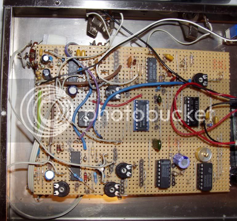
So I broke all the rules - you see those two chips in the middle, on the left a 4049 hex buffer and on the right the mighty SAD 1024 bucket brigade delivered to me on a mountain top in Utah while on holiday in the USA (when it only took 20 minutes to get in!). The clock is a 4047 and 4007 for voltage control - no noise reduction, output filter just in the regeneration!
Stephen
 
[quote author="StephenGiles"] the mighty SAD 1024 bucket brigade delivered to me on a mountain top in Utah while on holiday in the USA (when it only took 20 minutes to get in...[/quote]

:shock:

...a gift from the Gods??

Can't find any of those old analog BBD IC's for love 'nor money!!

Mark
 
Stephen
Do you have a piccie of the underside of the perfboard - so I can get an idea how you did the connections

regards
SImon
 
...a gift from the Gods??
Can't find any of those old analog BBD IC's for love 'nor money

Mark, try Steve Daniels at Smallbear in New York- he's just reopened after a break and his stock list should be on line. I'll have a look for the link.

Do you have a piccie of the underside of the perfboard - so I can get an idea how you did the connections

uk03878 - It's veroboard, see Mark's tutorial above!
Stephen
 
Back
Top