Another hybrid mic preamp

GroupDIY Audio Forum

Help Support GroupDIY Audio Forum:

This site may earn a commission from merchant affiliate links, including eBay, Amazon, and others.
Something was bothering me about this schematic. When I started to question the issues around the coupling cap placement, versus some alternatives, I noticed that the feedback R's seemed to be providing positive rather than negative feedback. Since no one else seemed to notice this I thought I'd better investigate before crying out.

I've just had another very amusing time with a simulator, trying to make sense of things.

It's a long story, but the performance with circuitmaker's ideal opamps is perhaps rather misleading. Astonishingly, to me at least, it seemed to not care whether the 10k feedback R's were hooked up as shown, or hooked up so as to provide more obviously actual negative feedback! I d.c. coupled the circuit and used resistors for input current sources, but otherwise things were basically the same topology.


Once I stuck a TL072 in the first opamp position though, things latched up soundly on turnon, whereas with the feedback resistors swapped things work fine. Also, now the expected signal inversion between one base and collector is as expected.

At root I think: when you really get into this type of topology, you realize that there are a whole bunch of loops to be considered, and it gets pretty hairy in a hurry.

When the circuit is a.c.-coupled with the positive feedback it does oscillate with a relaxation-osc character based on the coupling taus. Maybe there is some bizarre compensation that would restore the peculiar result gotten with the ideal (openloop gain 100dB, no rolloff, large input Z, zero output Z) opamps, but the circuit with the 072 didn't require compensation (I did use an ideal inverter for the second opamp stage though).
 
[quote author="bcarso"]Something was bothering me about this schematic. When I started to question the issues around the coupling cap placement, versus some alternatives, I noticed that the feedback R's seemed to be providing positive rather than negative feedback. Since no one else seemed to notice this I thought I'd better investigate before crying out.

I've just had another very amusing time with a simulator, trying to make sense of things.

It's a long story, but the performance with circuitmaker's ideal opamps is perhaps rather misleading. Astonishingly, to me at least, it seemed to not care whether the 10k feedback R's were hooked up as shown, or hooked up so as to provide more obviously actual negative feedback! I d.c. coupled the circuit and used resistors for input current sources, but otherwise things were basically the same topology.


Once I stuck a TL072 in the first opamp position though, things latched up soundly on turnon, whereas with the feedback resistors swapped things work fine. Also, now the expected signal inversion between one base and collector is as expected.

At root I think: when you really get into this type of topology, you realize that there are a whole bunch of loops to be considered, and it gets pretty hairy in a hurry.

When the circuit is a.c.-coupled with the positive feedback it does oscillate with a relaxation-osc character based on the coupling taus. Maybe there is some bizarre compensation that would restore the peculiar result gotten with the ideal (openloop gain 100dB, no rolloff, large input Z, zero output Z) opamps, but the circuit with the 072 didn't require compensation (I did use an ideal inverter for the second opamp stage though).[/quote]

Good catch... I'm so used to that general topology that I didn't bother to check. Pins 2 and 3 are reversed on the first opamp, or the 10K feedback Rs could go to the other input transistors.

As I posted earlier in this thread this topology needs (in my experience) a RC between pins 2 and 3 of that first opamp to compensate for the delay of the second opamp.

Yes, there is more going on than obvious at first glance, despite using only two opamps. When I first saw this topology while working at Peavey back in the mid '80s I wanted to use my more familiar 3 opamp approach but after discussing with the engineer already using this, it pretty much gets the job done with one less opamp (very much in the Peavey philosophy to save $0.13 per input).

I have nothing to offer about computer simulation but know from lots of hands on, if you lose the 470pf between input emitters, add an RC between pins 2 and 3, and use 072 or similar opamps this topology will work respectably well. Given a less price sensitive environment I'm inclined to fall back on the more comfortable (to me) 3 opamp approach using a 3rd opamp stage to SE and forward reference the two gain stages. Of course this means even more parts for someone wanting differential output in an outboard mic pre, but 99.9% of my pre designs were inside a console or mixer and even then, later insert points were routinely un-bal SE.

JR

PS: Do many people just post "what-if" schematics? I pretty much ASSumed it was functional and the poster was looking for input on how to improve or tweak. I have lots of what if schematics in notebooks that I doubt will work as drawn. My bad (again) for making the ASSumption.
 
[quote author="JohnRoberts"]

PS: Do many people just post "what-if" schematics? I pretty much ASSumed it was functional and the poster was looking for input on how to improve or tweak. [/quote]

Oh sure, there's plenty of that. Sometimes we are vouchsafed a bit more information as to the status, but it's all good. I worry sometimes that people will plow into layout before they know that the circuits work, the art of breadboarding being one seemingly out of fashion these days, but that's about the worst damage to be done.

Meanwhile, I did get the "ideal" opamp positive-feedback version to oscillate with just a little in the way of feedback and other capacitance, so the simulator does not lie consistently :razz: I will say that this is one of the most bizarre misbehaviors that I have ever seen with Spice.
 
[quote author="bcarso"]

Oh sure, there's plenty of that. Sometimes we are vouchsafed a bit more information as to the status, but it's all good. I worry sometimes that people will plow into layout before they know that the circuits work, the art of breadboarding being one seemingly out of fashion these days, but that's about the worst damage to be done.

Meanwhile, I did get the "ideal" opamp positive-feedback version to oscillate with just a little in the way of feedback and other capacitance, so the simulator does not lie consistently :razz: I will say that this is one of the most bizarre misbehaviors that I have ever seen with Spice.[/quote]

That's my basic complaint about computer sims, it seems you need to already know what you don't know to get it right... Oh well I'll just sit on the Luddite bench and muddle along.

I continue to be impressed with operations like that satellite that intentionally crashed into a moving comet (?). They apparently got the simulations right on that one, although there may have been some mid flight windage adjustments. At the closing speed they dealt with it was pretty impressive targeting.

JR
 
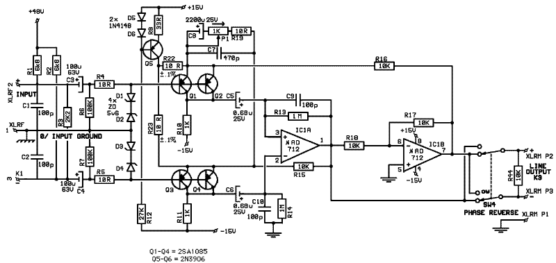
Here's the new drawing:

TFE-3_sch02.gif


[quote author="bcarso"]Something was bothering me about this schematic. When I started to question the issues around the coupling cap placement, versus some alternatives, I noticed that the feedback R's seemed to be providing positive rather than negative feedback. Since no one else seemed to notice this I thought I'd better investigate before crying out.[/quote]

I changed the first op amp pins configuration to correct position... my mistake!

The 5532 IMO is the wrong part for that slot.

I have changed it with the AD712 (BiFET)

[quote author="JohnRoberts"]Using two uncorrelated current sources means their noise will combine in the mic preamp outputs. One current source evenly split between the two will be coherent and so it's noise would cancel out. There would be some improvement from shorting the two current source emitters together as that would force the noise voltage to be the same but mismatched Vb-e between the two would cause unequal outputs.[/quote]

and the single ccs looks as an improvement...

PS: Do many people just post "what-if" schematics? I pretty much ASSumed it was functional and the poster was looking for input on how to improve or tweak.

As soon as I build it on a breadboard I will post the behaviour and results of the 'real life' device, and check for the RC network between pins 2 and 3 of IC1A.

:roll:

Val
 
[quote author="Val_r"][quote author="JohnRoberts"]Using two uncorrelated current sources means their noise will combine in the mic preamp outputs. One current source evenly split between the two will be coherent and so it's noise would cancel out. There would be some improvement from shorting the two current source emitters together as that would force the noise voltage to be the same but mismatched Vb-e between the two would cause unequal outputs.[/quote]

and the single ccs looks as an improvement...[/quote]
Now you have R22 and R23 in parallel with the gain setting network.

[quote author="Val_r"] :roll: [/quote]
Indeed.

JDB.
 
[quote author="Val_r"]Here's the new drawing:

TFE-3_sch02.gif


[quote author="JohnRoberts"]Using two uncorrelated current sources means their noise will combine in the mic preamp outputs. One current source evenly split between the two will be coherent and so it's noise would cancel out. There would be some improvement from shorting the two current source emitters together as that would force the noise voltage to be the same but mismatched Vb-e between the two would cause unequal outputs.[/quote]

and the single ccs looks as an improvement...

As soon as I build it on a breadboard I will post the behaviour and results of the 'real life' device, and check for the RC network between pins 2 and 3 of IC1A.

:roll:

Val[/quote]

As I mentioned before I know that this topology can work fine when properly dialed in.

WRT to your current source splitting resistors, use of 2x10 ohm means you will have a 20 ohm R in shunt across your gain pot. These Rs need to be more like 1k or larger to get a more useful gain range.

While there will be a first order cancellation of current source noise by using just one, I'd also be tempted to reduce it further at the source. Perhaps add a few more diode drops and use a larger emitter resistor. Also consider adding a capacitor shunt across the diode string to reduce noise there. Perhaps you can experiment with substituting a different device for 3906. 4403 is not very expensive and should be better than 3906 for noise.

I still don't understand the utility of a 470pF across the gain pot? RC across first opamp inputs provide adequate stability and don't alter closed loop gain.

100pF at C9/10 looks large to me (I'd start with 5-10pF).

There are probably other things I'd do differently, as previously discussed but this is the short list of what I believe could have more apparent audible consequences. I am not familiar with the opamps suggested but if they are modern Bifets they should be fine.

JR
 
[quote author="Val_r"]
I changed the first op amp pins configuration to correct position... my mistake!

[/quote]

I believe what you really want to do is swap the connections of the 10k feedback resistors (R15, R16)---leave the opamp polarity as it was, since you want the feedback C to go from inverting in to output as it was originally.

Also, now the current-sharing resistors R22 and R23 are dominating the impedance between the emitters. They need to be much larger, within the constraints of voltage drops. EDIT: Sorry to reiterate this---I see now that jd already mentioned it.
 
If you start with the very first schematic, as far as global feedback goes it's only the R15-16 feeds that are wrong. The local feedback cap in the first opamp is appropriate.

As far as the current sources, if one wants them I would look at what the minimum gain and maximum input level constrains things to, and then make the emitter R's of the sources larger and the base-to-rail voltages commensurately so. You will still have a contribution of base current shot noise, but the equivalent input voltage noise of the transistors will be a small contribution. This approach is more practical I think than using a single current source due to the problem with the current sharing R's.

I think, ultimately, I would explore d.c. coupling and a servo, but that turns things into a whole different design. What the thing will do now at very low frequencies should be examined.

I don't know what C7 is supposed to do either. It doesn't look appropriate for all closed-loop gains in any case, if it is there to tweak HF gain at some given pot position.
 
[quote author="bcarso"]

I believe what you really want to do is swap the connections of the 10k feedback resistors (R15, R16)---leave the opamp polarity as it was, since you want the feedback C to go from inverting in to output as it was originally.

Also, now the current-sharing resistors R22 and R23 are dominating the impedance between the emitters. They need to be much larger, within the constraints of voltage drops.[/quote]

What Brad said..... now both inputs and 10 Ks wrong.... and I'm still taking too much for granted.

To better visualize the feedback loops, when properly configured the opamps work to keep the bias current flowing in the input devices constant (give or take an AC error current equal to the opamp's input AC error voltage divided by collector load). If the upper pair (Q1,2) receives an up/down input, it generates an inverted down/up signal at their collector. This down/up signal is fed into the inverting input of the first opamp and creates an up/down signal again at it's output. This amplified up/down output signal is then applied through a 10K resistor to the emitters of the upper pair to close that loop. The inversion in the input transistors makes this look like negative feedback to the opamp with a FF (feedback factor) of 1/10 so stable.

The lower input pair (Q3,4) have their inverted collector signal fed into the first opamp’s + input so it emerges at that output amplified but in the same phase (still down/up). It is then inverted by the second opamp to be back in the correct phase (up/down) to be fed back to the lower pair's emitters through the second 10K. Again this looks like negative overall feedback to that first opamp with a similar 1/10 FF, but now with the additional delay of the second opamp in that feedback path. It may require additional compensation depending upon the opamp’s characteristics while the FF of only 1/10 is somewhat helpful for stability (I have received some debate from circuit sim’ers on that point but it looks pretty straightforward to me.)

JR
 
[quote author="JohnRoberts"]
That's my basic complaint about computer sims, it seems you need to already know what you don't know to get it right... Oh well I'll just sit on the Luddite bench and muddle along.

JR[/quote]

I will readily admit that I fought sim programs for a long long time. I was especially put off by the requirement of manually listing nodes, although it really isn't that bad.

When I had had enough of being at the mercy of board layout folks redrawing my fountain pen schematics wrong, and when a tech simulated some Friend-Delyannis filters designed by another engineer and proved to his satisfaction that the simulation agreed with his breadboard and that they all oscillated, I dipped my toe in the water and installed an early version of Circuitmaker. This program was clumsy, buggy, limited, and the graphics were ugly. But the convenience of automatic extraction of the net-node information was nice, and of course I went in knowing a fair amount about what to expect, so when the program lied I was generally able to cope.

Brad Plunkett, whom I've worked for and with on and off since 1990, and only about 7.5 years older, continues to regard me as having gone over to the Dark Side of the Force. But when I was still consulting adjacent to him at a client's, he was not too proud to resist coming to me, from time to time, to do some quick sims of his designs (done in BradCAD, i.e., pencil and paper). He still comes up with clever ideas and topologies, but he is reluctant to push the performance envelope and explore just how well things could work. And this is usually completely adequate for the task at hand.

I still do a lot of pen and pencil drawing at the conceptual level, and even a fair amount of calculation on my HP15C. But I can do a lot of interesting stuff with the last version I bought of Circuitmaker. What I should do is get well-versed in one of the big maths packages. But then I'm not sure how much longer I really want to do electronics---it's beginning to lose its novelty after nearly 40 years.
 
[quote author="mediatechnology"]

Wavebourne's Yamaha post is an interesting cite as it appears to have a 100 pF (but the dots are very small on that image) between the op amp inputs as John R has discussed in this topology. No C across the gain resistor/pot which intuitively looks wrong.[/quote]

The Yami pre is a different animal although I'd swear somebody posted that or a very similar variant recently to some other thread. In the Yami the NPNs hanging off the collectors serve as the inverting gain stages with local feedback to keep the input devices constant current and the first opamp is a basic differential to SE convertor similar to the 3 opamp hybrids. I don't know why there's a cap between + and - inputs of that diff amp but I've never messed with that particular topology.

JR
 
[quote author="JohnRoberts"][quote author="mediatechnology"]

Wavebourne's Yamaha post is an interesting cite as it appears to have a 100 pF (but the dots are very small on that image) between the op amp inputs as John R has discussed in this topology. No C across the gain resistor/pot which intuitively looks wrong.[/quote]

The Yami pre is a different animal although I'd swear somebody posted that or a very similar variant recently to some other thread. In the Yami the NPNs hanging off the collectors serve as the inverting gain stages with local feedback to keep the input devices constant current and the first opamp is a basic differential to SE convertor similar to the 3 opamp hybrids. I don't know why there's a cap between + and - inputs of that diff amp but I've never messed with that particular topology.

JR[/quote]

Anyway it sounds very clean; the DR is unbelivable wide, THD is very low, though I've sold the console last Friday in favour of tube mic pres I've developed.
 
[quote author="bcarso"]
I still do a lot of pen and pencil drawing at the conceptual level, and even a fair amount of calculation on my HP15C. But I can do a lot of interesting stuff with the last version I bought of Circuitmaker. What I should do is get well-versed in one of the big maths packages. But then I'm not sure how much longer I really want to do electronics---it's beginning to lose its novelty after nearly 40 years.[/quote]

Dont know bout rest of them, but Matlab is joy joy joy. And then more joy.
When I was in school (early part of this century) Spice and derivates were
just mentioned here and there, with idea that you are not EE if you cant
calculate at least DC conditions by hand (and without HPsomething !!!).
OTOH Matlab knowhow was absolute requirement.
And, on a bonus side, Matlab can be as deep as you want it to.
No steep learning curve. And has top notch help. Do I sound like salesman?

Sorry for OT shit
urosh
 
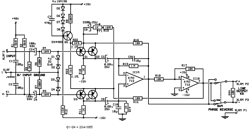
[quote author="mediatechnology"]I know that this was discussed earlier, but aren't pins 2 and 3 (on the latest drawing) for the AD712 reversed?[/quote]

Now it should be correct...

TFE-3_sch03.gif
 
[quote author="Val_r"]

Now it should be correct...

[/quote]

2200u cap in series with 1K pot is shorted. It wont do much here. And,
isn't gain range around 40 dB?

cheerz
urosh
 
[quote author="Val_r"]Now it should be correct...[/quote]
Nope.

Your current source is trying to source 20mA. That's 5mA per 2SA1085; are you sure that's the correct bias for optimum noise with a source impedance of ~50 Ohm ? Worse, that 20mA split over those two 1k5 resistors (why 0.1%?) will try to drop 15V between the collector of Q5 and the emitters of Q1...Q4, which isn't going to happen with the +15V supply you show.

Why do you think a single current source plus two 1k5 resistors will be (noticeably) less noisy than two current sources whose noise current is at least partly cancelled through your gain network ? You can do a Delta-Y transform to see the exact impact. There's a saying in the software industry: Premature optimization is the root of all evil. Get it working first, then tune it for lowest noise.

Why do you have a 100k input bias resistor to ground which will reverse-bias the input capacitors, especially with the huge amount of current you're driving through Q1-Q4 ?

Don't take this the wrong way, but instead of rapid-firing revisions of your circuit diagram at us, why don't you just sit down and do some calculations on it ? It'll help your insight; I know it has helped me in the past. Use a simulator if you must, but try to understand how it's getting at its results. Breadboard the thing, if it turns out you've built an oscillator instead of an amplifier (happens to all of us), tweak and measure and tweak some more. Like JR said, this topology can work fine when properly dialed in, so at least you know that you're not going down a dead-end street.

Good luck, and let us know how you get on,

JDB.
 
[quote author="jdbakker"]
Your current source is trying to source 20mA. That's 5mA per 2SA1085; are you sure that's the correct bias for optimum noise with a source impedance of ~50 Ohm ? Worse, that 20mA split over those two 1k5 resistors (why 0.1%?) will try to drop 15V between the collector of Q5 and the emitters of Q1...Q4, which isn't going to happen with the +15V supply you show.[/quote]
I can't tell from observation if that current source is closer to 15 or 20 mA but agree it looks a little strong, and FWIW nominal mic source impedance is 150-200 ohms which might also suggest a lower current density. I might also be inclined to run the bias string a little lighter (does it really need 2 mA? and 470 pf isn't going to do much filtering either. I lean more to 1k than 1.5k for splitters unless you come down on current. The voltage drop here will reduce input CM range so it's a tradeoff between that and higher minimum gain.

[quote author="jdbakker"]
Why do you think a single current source plus two 1k5 resistors will be (noticeably) less noisy than two current sources whose noise current is at least partly cancelled through your gain network ? You can do a Delta-Y transform to see the exact impact. There's a saying in the software industry: Premature optimization is the root of all evil. Get it working first, then tune it for lowest noise.[/quote]
I suspect the single current source change is in response to my suggestion so I will answer. The use of two separate current sources fed into the two emitters separately are incoherent and look to me like they combine rather than cancel. By using just one and feeding it equally into both emitters it is now a single common mode signal and will cancel. Note: while perhaps not immediately obvious the quality of this CMR will be impacted by precision of all 4 10K resistors too.

A second consideration which hasn't been mentioned, this approach should also improve HF CMRR. While there would be a first order matching of the output capacitances using two similar current sources, use of just one CM through resistors is much better matched and lower current at HF.
[quote author="jdbakker"]
Why do you have a 100k input bias resistor to ground which will reverse-bias the input capacitors, especially with the huge amount of current you're driving through Q1-Q4 ?[/quote]
Unless the +48V is is shorted to ground when turned off where is the dc path to reverse bias the subject capacitors? There are plenty of nits to pick about this design but that's a minor one.
[quote author="jdbakker"]
Don't take this the wrong way, but instead of rapid-firing revisions of your circuit diagram at us, why don't you just sit down and do some calculations on it ? It'll help your insight; I know it has helped me in the past. Use a simulator if you must, but try to understand how it's getting at its results. Breadboard the thing, if it turns out you've built an oscillator instead of an amplifier (happens to all of us), tweak and measure and tweak some more. Like JR said, this topology can work fine when properly dialed in, so at least you know that you're not going down a dead-end street.

Good luck, and let us know how you get on,

JDB.[/quote]

Agreed, most of our comments would make themselves quite apparent once the circuit was bread boarded, especially that part about the input pins being scrambled. I missed those very obvious errors (twice) because I wasn't proof reading his schematic entry ability, but looking at the underlying design. The definitive way to find all such errors is IMO on the bench (or circuit sim if that's your preference).

JR
 
[quote author="jdbakker"]

Don't take this the wrong way, but instead of rapid-firing revisions of your circuit diagram at us, why don't you just sit down and do some calculations on it ? It'll help your insight; I know it has helped me in the past. Use a simulator if you must, but try to understand how it's getting at its results. Breadboard the thing, if it turns out you've built an oscillator instead of an amplifier (happens to all of us), tweak and measure and tweak some more. Like JR said, this topology can work fine when properly dialed in, so at least you know that you're not going down a dead-end street.

Good luck, and let us know how you get on,

JDB.[/quote]

Thanks, that is my intention !

:roll:
 

Latest posts

Back
Top