Another hybrid mic preamp

GroupDIY Audio Forum

Help Support GroupDIY Audio Forum:

This site may earn a commission from merchant affiliate links, including eBay, Amazon, and others.
[quote author="JohnRoberts"] In the Yami the NPNs hanging off the collectors serve as the inverting gain stages with local feedback to keep the input devices constant current and the first opamp is a basic differential to SE convertor similar to the 3 opamp hybrids.[/quote]

Thank you very much for explaining that. I noticed right away that the input pairs were reversed from the compound pairs I'm used to seeing.

Hee hee..... Yami. :grin:
 
[quote author="recnsci"]

Dont know bout rest of them, but Matlab is joy joy joy. And then more joy.
When I was in school (early part of this century) Spice and derivates were
just mentioned here and there, with idea that you are not EE if you cant
calculate at least DC conditions by hand (and without HPsomething !!!).
OTOH Matlab knowhow was absolute requirement.
And, on a bonus side, Matlab can be as deep as you want it to.
No steep learning curve. And has top notch help. Do I sound like salesman?

Sorry for OT shit
urosh[/quote]

Yeah that's what I have in mind, as soon as I can afford the time and the money. As the guy on MAD TV says, it will take it to a Whole Nuther Level.

Meanwhile I talked to Plunkett yesterday and he let it slip that's he downloaded some freeware sim program and is using it now. Another Jedi to the Dark Side muahahahaha....
 
I mounted the circuit (actually the double CCS version) on breadboard, so that I could easily make changes and compare the results.
I was so lucky that it did not turn to be an oscillator !! :))

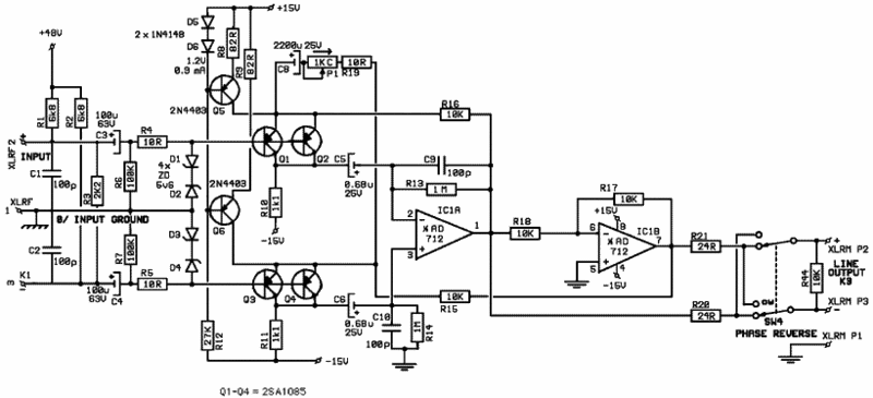
This is the actual circuit:

Tfe3_sch03.gif


The maximum differential gain, measured at the balanced load (8.6k), reaches 63dB ( = 1,400 V/V).

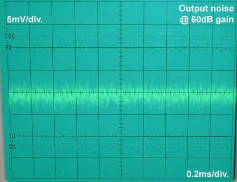
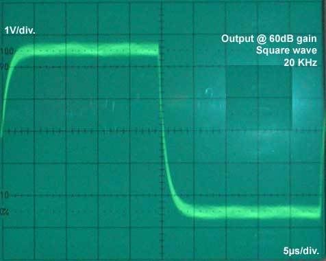
You can see the pics I took from my scope:
the output noise, and the squarewave response at 20kHz (only one phase shown).

scope01.jpg


scope02.jpg


Next, I want to try the single ccs version.

I did my calculation, and found that for a 150-ohm source, the optimal collector current for each 2SA1085 should be -3.23 mA (-6.46mA for each rail),
the short-circuit noise of input stage:
Ena = kT*sqr root(2/q*Ic) =
= 2.575 x 10 ^ -10 V/root Hz

while differential base current noise turns out to be:
Ina = 2.43 x 10 ^ -12 A/root Hz

I did also have a listen with a Shure SM 57 microphone into a 150-ohm headphone: quite respectable nice sound, I found it to be fast enough for my tastes.
I used the value of 100p for C9 and C10 to better suppress the spurious oscillations, that the 10p value didn't seem to attenuate.

As always, any comment or suggestion is more than welcome.

Thank you.

Val.
 
Did you check stability at lowest gain? At 60 dB you should not run into stability problems unless you have some crosstalk from output to input (which might easily happen on breadboard).

Samuel
 
looks good so far... and not to argue with success... but.

I am not sure I like going all the way down to 100 pf at C9 and C10. While it's arguably adding more parts, I've seen this topology commonly stabilized with a RC directly across IC1A + and - input pins. I'd prefer something more in the range of 5-10 pF at C9-C10 and then look at what is required in a RC across the opamp input to finish the job.

Perhaps start with just a R first to see how much it takes to clean it up. Then drop that R value in half or so and see how small of a C you can get away with in series to make it stable with minimal impact to audio frequency band.

I know, not very scientific but I'm from the generation that grew up using decade boxes full of resistors and capacitors on the bench to make circuits work with whatever value it needed... You always calculate first, then you do whatever it takes.

JR
 
[quote author="Samuel Groner"]Did you check stability at lowest gain? At 60 dB you should not run into stability problems unless you have some crosstalk from output to input (which might easily happen on breadboard).[/quote]

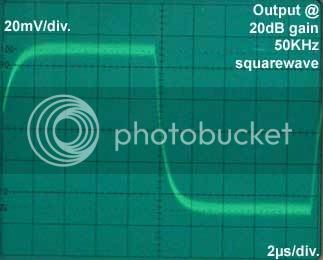
At lowest gain I did not go over stability problems, as shown in the pic below, taken at 50kHz @ 20dB of gain.

scope03.jpg


[quote author="JohnRoberts"]I am not sure I like going all the way down to 100 pf at C9 and C10. While it's arguably adding more parts, I've seen this topology commonly stabilized with a RC directly across IC1A + and - input pins. I'd prefer something more in the range of 5-10 pF at C9-C10 and then look at what is required in a RC across the opamp input to finish the job.[/quote]

I tried to put a resistor between pins 2 and 3, in various values, but it seems that it worsen the performance... anyway will investigate further.

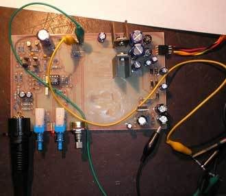
This is the actual mounted board of the circuit...

board.jpg


Respect,

Val.
 
You ripped the Valley People.
Didn't John Roberts design for VP?
Hang a good 600, like an HS 56 on the ass end and your output gremlins will disappear.
The opamp I/O is tricky, it does not always pair up nicely with the following piece of equipment.

I always wondered if current draw was the same for both half cycles in the output section. If not, make sure you have good pwr supply rejection.
 
[quote author="CJ"]You ripped the Valley People.
Didn't John Roberts design for VP?
Hang a good 600, like an HS 56 on the ass end and your output gremlins will disappear.
The opamp I/O is tricky, it does not always pair up nicely with the following piece of equipment.

I always wondered if current draw was the same for both half cycles in the output section. If not, make sure you have good pwr supply rejection.[/quote]

No, I did not have any connection with VP other than using their Transamps in one console series and VCA in a compressor back in '80s (LOFT). I did get to know and respect Paul Buff as a brilliant designer.

FWIW the particular topology explored in this thread is more like the pre's used at Peavey (and probably elsewhere) than VP and my earlier design work which was inspired by Buff's work and others. The Transamp used two hybrid gain stages in parallel into a following differential amp. While I have seen that topology credited to Cohen around here, AFAIK Buff developed it, and it is still my preference when not shaving pennies in a design.

While I'm not personally familiar with the AD 712 it looks like an OK part and I don't expect loading down the output to be a useful technique for stabilization.

JR
 
[quote author="Samuel Groner"]
So it was stable at 20 dB with 10 pF instead of the final 100 pF?

Samuel[/quote]

With 10p, I had some oscillations in the squarewave at LF, that the 100p value have mitigated.

I think I should investigate further with the RC network at the first opamp inputs.

My listening impressions:
While I have always dealt with tubes, this time I am missing part of the sweetness and mellowness of typical tube builds, but I was still pleased with the velocity this kind of preamp is able to offer.

[quote author="CJ"]You ripped the Valley People.
Didn't John Roberts design for VP?[/quote]

We continue inventing the wheel :wink:

Respect,

Val.
 
sorry John, I had you confused with a guy who helpped BYacey with the VP design.
I have his emails around somewhere.
He was in some way connected with VP, and had some good insights on this type of design.
I thought the guy was in MS also, but maybe it wa Nashville.

anyway, the vp circuit is available at vacuumbrain.com if you wan t one with backwards opamp polarity also.
:oops:

http://www.vacuumbrain.com/docs/valley_people.html
 
[quote author="CJ"]sorry John, I had you confused with a guy who helpped BYacey with the VP design.
I have his emails around somewhere.
He was in some way connected with VP, and had some good insights on this type of design.
I thought the guy was in MS also, but maybe it wa Nashville.

anyway, the vp circuit is available at vacuumbrain.com if you wan t one with backwards opamp polarity also.
:oops:

http://www.vacuumbrain.com/docs/valley_people.html[/quote]

No worries,

That schematic is news to me. AFAIK the green potted Transamp looked more like the schematic published by Cohen, than this. Perhaps they changed horses later. (I can't open the word doc on my MAC, may look with another computer).

Buff was and probably still is in Nashville area. I'm in MS because I came here 20 years ago to work for Peavey and it is cheap to live/work here. These days it's getting too cold for me here, may need to move closer to the equator.

(edit) I opened the word file, and indeed there's an app note from Valley showing the 2 opamp approach. There is no mention or suggestion that this is the same as a Transamp, which I suspect they held proprietary. AFAIK they didn't pot that for purely thermal reasons. I suspect they were highly motivated to sell lots of matched transistors to support the numbers needed to get enough good matches.

JR
 

Latest posts

Back
Top