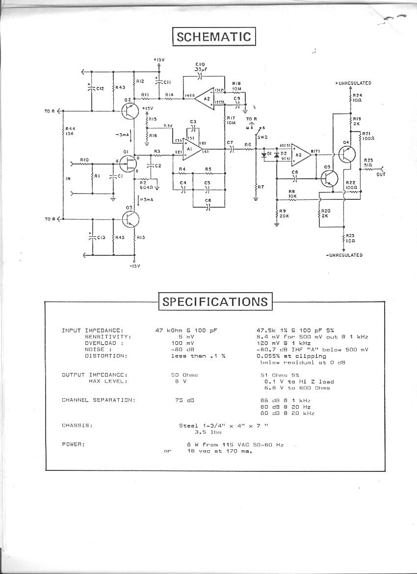
Benchmark Mic Pre Schematic from 1984

GroupDIY Audio Forum

Help Support GroupDIY Audio Forum:

This site may earn a commission from merchant affiliate links, including eBay, Amazon, and others.
When ROHM stopped making the 737/786 series they surely gave users a last chance life time buy, order opportunity. My suspicion is that active users transitioned to the Toshiba parts quicker than anticipated by distribution channels. I was not aware Toshiba parts were that close in performance, but if I was an active user at the time, I would have figured that out.

JR
 
[quote author="Samuel Groner"]
Easy to protect against with simple clamp e-b.
Which is built-in in the LM394, at least for the TO-78 package.

Samuel[/quote]

I find it more than a little confusing that they show a diode for one package and not the other (diodes probably in both)? Their spec sheet clearly describes a diode designed in as a clamp e-b. There is also apparently a parasitic diode clamping lowest voltage emitter to substrate which appears to be floating otherwise.

In their own application notes they add clamp diodes (2x 1n457) b-b in a low drift amp that seems redundant if built in b-e clamps were effective, unless they're just using them for faster recovery (in a low drift amp)?

I found the 394s good for their brief moment as the quiet guy with good matching, but found them too expensive for logging apps and not all that robust. I think I added clamp diodes, but I only used them in a few discrete opamps decades ago.

JR
 
As I mentioned earlier in this thread I published a phono preamp kit in early '80s. I think '81? I couldn't find the original article in a quick search but found two different reviews of the preamp in '83.

P10.gif


This image is of the JFET MM version, I didn't scan the MC preamp variant when I scanned this one (I can if it's really important, just not right now). I used the same exact low noise xstors as Burdick in my MC kit. He probably saw the same IEEE journal article that I did. Coincidentally that article also mentioned the very low noise teledyne crystallonics JFET he cited in bottom left hand corner of his drawing so that's probably where it came from.

My published circuit (1981?) was similar but I used TL074 instead of 5532, and operated at fixed gain. Since I was interfacing with a MC phono cart, I didn't require the front end phantom power paraphernalia. Since it was printed in Popular Electronics I'd say it was public domain years before Cohen et al. ROHM even thanked me for getting them some publicity for their low noise parts.

I don't claim originality for this topology, I first saw it used by Paul Buff inside his "transamp" years earlier (AFAIK not published). FWIW Burdick's high and low gain CM trims looks reminiscent of transamp application note.

I used transformer mic preamps in my early Loft consoles (late '70s) but rolled my own transformerless around the 737s after I read the IEEE paper and chased them down. As I recall ROHM was the importer not manufacturer. ROHM ended up buying the smaller Japanese company that made them.

Part of the secret sauce in Buff's transamp was the low noise transistors, (he hand selected medium power devices) but after ROHM introduced these low noise parts, off the shelf was quite adequate.


JR
 
Cohen shows the transamp topology in his paper (fig. 2). What's new about his design is the DC coupling (and perhaps the fully differential topology). The Benchmark circuit shown is very close, but uses AC coupling to the second stage.

Samuel
 
If you mean differential input with gain adjustment between emitters, I saw such Altec preamp dated much earlier. If you mean usage of opamps there, do somebody really need to patent usage of them?
 
I suppose that the AC-coupling to the second stage in Burdick was due more to 2SB737 matching and tracking than a fundamental topology difference.
For sure they are essentially pointless as the second stage has low gain and its output is AC-coupled itself.

Samuel
 
[quote author="mediatechnology"]
I may be mistaken but that topology of input (not the fully-balanced part later in the paper) is often attributed to him. He doesn't attribute it to himself nor does he cite a source for it. In reading his paper, I thought he did it. But he never actually says that and I wonder if many of us have made the mistake if thinking it was his. He could have just thought of it independently.[/quote]

It reminds me graffiti in some places, like: "John Smith Was here" :green:
So what?
 
Not to agree with Wavebourn (don't tell him) but yes, the general topology had been around, while early versions that I recall didn't close the feedback loop all the way around the input devices.

The concept of combining an opamp with a discrete device either in front of, behind, in the feedback path, or even in power supply leads, was also well explored in the literature. In Motchenbacher and Fitchen's low noise design (C.1973) they show the single ended transistor front end with opamp wrapper. In hindsight it seems a logical extension to combine two for balanced input, but hindsight is always crystal clear.

The milestone or transition that I recall in the early '80s was discrete devices finally becoming quiet enough to replace transformer front end mic preamps. IIRC that IEEE paper was mainly about low noise devices, not topologies, but that was decades ago so I'm not very confident in my recollection.

The Cohen schematic is a clean but not very complete preamp design. The Burdick design is somewhat less parts intensive than the transamp, since he eliminates the current sources used to bias up the input devices by biasing them via the feedback Rs, while his cap coupling at the final differential stage is not only unnecessary but adding a potential source of LF CMR error.

I don't know if it's worth parsing out the subtle differences between all of these. If you really want to know, ask Paul Buff how he came up with his design. That's the first example I saw with all these moving parts in that general configuration. I wasn't even aware of the Cohen paper until I started lurking here.

JR

PS: My MC kit just used the same schematic as FET version with a small inset showing the two bipolar transistors, so it may be easier to just look at FET schematic and imagine PNP bipolars in place of FETS. Associated parts are reversed for opposite polarity. Collector load R pulls down to V- instead of up to V+ for FET drain, and interior opamps biased up to +V/2 to provide device operating current via feedback resistors.
 
[quote author="JohnRoberts"]
The concept of combining an opamp with a discrete device either in front of, behind, in the feedback path, or even in power supply leads, was also well explored in the literature. In Motchenbacher and Fitchen's low noise design (C.1973) they show the single ended transistor front end with opamp wrapper. In hindsight it seems a logical extension to combine two for balanced input, but hindsight is always crystal clear.
[/quote]

At the end of 70'th I used transistors in front of opamp, directly coupled, to amplify results of Doppler shifts in a microwave alarm detector. No doubt, I was not the first one who did that. Big deal, huh?
 
[quote author="mediatechnology"]Wavebourn: We don't you credit for it. Have you taken credit for it? Not here at least. So yes, what you have done is NO BIG DEAL. I think we can all agree on that.

EDIT: I'm also saying what Burdick did is no big deal. But, you won't ever "get" the point because you do not chose to.[/quote]

I always choose another point, that is in the future... Then go for it. :green:

If somebody reinvented a bicycle that does not mean he is standing on shoulders of somebody else who did that before. Did Sikorsky stand on shoulders of Leonardo da Vinci? If yes, we all stand on shoulders of Atlanteans, starting from Sumerians...
 
[quote author="mediatechnology"]Cohen in 1984 claims his figure 4 topology is "new." In the text he never said it was his topology, just "new." I need to dig through his references which are not cited for his figure 4 to see if there's anything there.[/quote]
"New" is a concept that's open to several interpretations. It may well have been new to him, in the form that he presented it. It may have been that he considered it new to the body of well-known published work.

A decade ago when I was still in research, and expected to publish new stuff to peer-reviewed conferences and journals, I found it pretty hard to be sure that my material was, well, new. Not only that, but it happened more than once that I encountered non-new material at such conferences, which had apparently slipped past the reviewers. And we had Altavista and later Google, and online access to oodles of published work.

[quote author="mediatechnology"]Cohen is often credited for this topology but I'm not sure that's fair.[/quote]
I'm not saying it is fair, but the fact that he's often credited with it does suggest that his is one of the earliest widespread open publications about this topology. If not, his claims of newness would have been denounced on the spot, no?

JD 'not affiliated with Graeme C' B.
[don't have the preprint myself, just read bits and pieces. While I don't value having the full picture at the $20 that the AES wants from a non-member, I sure would appreciate it if anyone could lend me a copy]
 
[quote author="mediatechnology"]Wavebourn - You're best ignored. I broke my own rule. And, by ignoring history I repeated a past mistake.

Many of us can learn from history. You obviously know everything. There are other people here - the rest of us - who can learn.

[/quote]

Yes, some people (like me) are not historians; we learn from history what to do and how to do, in future... It does not mean we are bad people; we probably have a different way of thinking, and deserve to live and to discuss topics like you...
 
There's a somewhat misleading drafting detail in that schematic: one might think, with the capacitor symbols and particularly with the "+" notations, that C3 and C4 were 'lytics and rather large in value. I see that ADI is inconsistent with their schematics. Sometimes the caps are shown with two straight plates, sometimes with the one plate curved, and in the above, one curved and with the plus sign.

The values are not given anywhere I've looked, but I would rest assured that they are relatively small.
 
[quote author="bcarso"]There's a somewhat misleading drafting detail in that schematic: one might think, with the capacitor symbols and particularly with the "+" notations, that C3 and C4 were 'lytics and rather large in value. I see that ADI is inconsistent with their schematics. Sometimes the caps are shown with two straight plates, sometimes with the one plate curved, and in the above, one curved and with the plus sign.[/quote]
The Dec '82 IEEE-article doesn't show C3,4 with the '+', but happens to have a plus-sign for all caps in the detailed schematic.

Moreover, if the polarity of an electrolytic cap would have been of significance here (which it isn't of course), then the simplified & detailed schematics would have been different w.r.t. C3,4-polarity.

The values are not given anywhere I've looked, but I would rest assured that they are relatively small.
FWIW, the Feb '82 ISSCC digest has a pic of the chip but no overwhelming cap-areas. A total of 75pF of MOS-capacitance is reported.
C3,4 value can be estimated from the input transconductance and the 25MHz GBW-product.


BTW, in general, I think that the words 'new', 'novel' and 'technique' are often a bit overused in articles. Some authors look a bit too eager to plant a flag and don't notice that isle they just landed on is already inhabited... :wink:

Regards,

Peter
 
[quote author="mediatechnology"]

A programmable instrumentation amplifier for 12b resolution systems
By Wurcer, S.; Counts, L.
This paper appears in: Solid-State Circuits Conference. Digest of Technical Papers. 1982 IEEE International
Page(s): 84 - 85
Feb 1982
Volume: XXV Issue:

The AD524, with a block diagram looking like this was published in 1982 at least two years prior to Cohen.

AD524_Block.jpg


Not Cohen but maybe Wurcer.[/quote]

There's a more serious drafting error where R56 and C4 is shown connected to collector Q2,4... doesn't anybody check their work?

This is consistent with my sense that the topology was known to those skilled in the art... The hard part was getting input devices quiet enough to eliminate transformer front ends. Even this chip appears to parallel input devices, presumably to lower noise voltage.

I don't know if cap coupling the inner loop is important. I've done it both ways. The LF pole frequency of that inner loop when cap coupled is pretty low and IMO not significant.

JR
 
I vaguely recall some old UREI design using an LM394 and some sort of opamp in the loop. Perhaps someone has that schematic fragment at hand. I don't think it was as elaborate as these more symmetrical topologies.

It's hard to proof drafting if you already know how the circuit works. I've blundered a few times when I let someone else do the drafting.

On the general subject of priority, I recently conceived of a topology that I wondered how people had missed. I hunted for it a while, came upon something closely related attributed to Hawksford, and eventually (thanks to posts by jcx, previously known as jcox, on diyaudio) discovered that it was described by Peter Baxandall in 1966. The nerve! Stealing my idea 42 years ago! It's also pretty clear that Hawksford was unaware of the Baxandall paper when he published in 1988.

So it goes.
 
The Roberts self-bias was March, 1981.
But still AC coupling to the opamps...

IIRC I've seen the topology under discussion dated in a schematic from ~1970, just can't remember where this was.

But the entire discussion seems somewhat pointless to me--Cohen has first published the topology to the audio community, that's what he get's (and should get) the credit for. Usually a "new idea" is around in many heads; its always about who publishes first.

C3 and C4 value can be estimated from the input transconductance and the 25 MHz GBW-product.
I get about 8 pF each, given the 1 MHz unity-gain BW and the 20k feedback resistors. Input transconductance does not appear in the according equation, as we are dealing with a CF system (this is IMO somewhat misleadingly formulated in the IEEE paper).

Samuel
 

Latest posts

Back
Top