Benchmark Mic Pre Schematic from 1984

GroupDIY Audio Forum

Help Support GroupDIY Audio Forum:

This site may earn a commission from merchant affiliate links, including eBay, Amazon, and others.
While I may win on number of eyeballs (ROHM got calls because of my article), I wasn't making a scientific presentation. I just wanted to sell some kits. I'm sure the editors called it new and improved... they wouldn't print any article that wasn't . :wink: I find it hard to ignore as publication. Such magazines are often cited in technical searches.

I had seen the general topology around. Like I said opamps wrapped around an input device was in M&F Low Noise Electronic Design, page 124 (c. '73). Converting that to an instrumentation amp topology does not seem like that much of a stretch, while admittedly they did not do so. Presumably for the lower noise of a single ended topology.

[Note: there are some subtle noise (especially noise current) cancellations related to shunting two inputs of an instrumentation amplifier together with a low impedance floating source while those same inputs enjoy a relatively high impedance wrt ground. I haven't seen this discussed in literature either. ]

I had used this topology and seen it used in mic preamps years earlier. the transamp was inside a potted module so not exactly common knowledge but the folks in the game probably knew what was inside (I did).
------
Publication, at least as far as the patent office is concerned also counts when you "sell" something, while showing at a tradeshow usually establishes publication for most things. AES journal should be peer reviewed, and I've seen a few snarky exchanges with referees, but they sure didn't ask me about this. :cool:
---------

I'm not sure I understand the significance of AC coupling the inner opamp loop? The phono preamps (both MM and MS version) I published were cap coupled, while I believe I may have used DC coupling in some console preamps I did around that same time frame (less parts). The main issue with DC coupling the inner loop is that you should AC couple the emitter gain resistor or select devices carefully to avoid eating up headroom due to input offset voltage.

The preamp variant already being used by Peavey when I got there in '85 was DC coupled there as I recall and used the 2 opamp, not three opamp version. I don't know how long they were using it before I got there (they were using the 2SD786 low noise npn) so not more than a few years if that.

Did Dove publish any of these approaches in his console series for Studio Sound? I don't recall the details but surely he covered mic preamps. When I wrote about consoles in 1980 I touted the transamp, since it was before I started buying the low noise 737s and rolling my own.

JR
 
[quote author="Samuel Groner"]
C3 and C4 value can be estimated from the input transconductance and the 25 MHz GBW-product.
I get about 8 pF each, given the 1 MHz unity-gain BW and the 20k feedback resistors. Input transconductance does not appear in the according equation, as we are dealing with a CF system (this is IMO somewhat misleadingly formulated in the IEEE paper).[/quote]
I didn't study the Wurcer/Counts Feb'82-ISSCC paper in more depth yet, was merely quoting here.
But FWIW, the Dec82 IEEE-article happens to repeat it (but now 22 i.s.o. 25 MHz).

Whatever; I guess at least one of you will be right here :wink:

Regards,

Peter
 
Sorry Mediatechnology for bad news;
this can't work at all as drawn, if a feedback resistor has high enough value to supply an adequate negative current to emitter.

[quote author="mediatechnology"]Forgot I had this one on the bookshelf...

Motchenbacher_Fitchen_LN_Design_Pg124.JPG


Motchenbacher and Fitchen - Low Noise Electronic Design, 1973.

Thanks for the cite John and Brad. If I hold it up to the mirror and squint I can see the second half of the differential pair form.

Must have been pretty well-known by 1984.[/quote]
 
[quote author="mediatechnology"]Perhaps you should call customer service at John Wiley and Sons and complain.[/quote]

Why? I don't like to complain. And I don't participate in threads about bad news. This one is interesting, because it is more technical than emotional.
On the picture you've posted an opamp needs to have a negative output shift to supply a transistor. The more of gain you need, the close the output voltage will go to the negative rail, until it stops working.
 
Your observation is correct, but the schematic is from a text book about design, and "schematic" in the pure sense of the word not a literal circuit plan.

From WIKI http://en.wikipedia.org/wiki/Schematic

"A schematic is a diagram that represents the elements of a system using abstract, graphic symbols rather than realistic pictures. A schematic usually omits all details that are not relevant to the information the schematic is intended to convey, and may add unrealistic elements that aid comprehension."

I believe the authors covered biasing devices (for low noise) in another chapter.

JR
 
[quote author="JohnRoberts"]

I believe the authors covered biasing devices (for low noise) in another chapter.
[/quote]

I hope so...

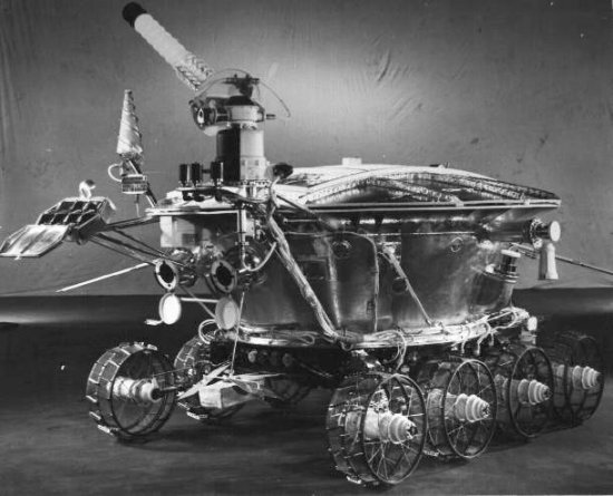
"We stole a file with plans of your 'Lunokhod', but building it we were getting T-34 tank! Why?"
"You should steal also all files with corrections and additions!"

lunokhod1.jpg

t-34-DNST8601537_JPG.jpg


Edit: changed a picture of Lunokhod since the old one disappeared...
 
[quote author="mediatechnology"]... If I hold it up to the mirror and squint I can see the second half of the differential pair form. ...
[/quote]

Wayne, that might be onset of double vision. That's why I have a strict rule not to hit the sauce until after 6PM, when I compose my replies to Consul's posts. :razz:

Actually this reminds me a bit of Comlinear's initially-granted patents for some of their complementary topologies for current-feedback amps. I don't know all of the inside details, but I think someone decided to go to the trouble of contesting them, and cited some fairly early work on amplifiers---maybe even the very common practice of feedback to the cathode of an input tube.
 
Actually it is Yamaha, and is very asymmetrical since transistor stages see very different loads.
And yes, each pair of transistors do the same as a transistor and an opamp do in your fig.1
 
[quote author="Wavebourn"]
mx400in.gif
[/quote]
Slightly different beast, that -- with local feedback through the complementary pair. Pretty much Rod Elliot's Project 66:

p66-f1.gif

discussed here by PRR et al. It's also used in at least one Behringer product (and likely several more; I suspect this is their 'IMP').

As for the schematic you posted: pity they spoil a perfectly good 2SB737 by running it so lean (~1mA) and adding R117/118. Then again, that's just the theory; it may well sound great.

JDB.
[never knowingly worked on or heard an MX400]
 
The playback preamp on the Tascam 38 was pretty similar to the Yamaha front end as well, that machine was available in the late 70's or real early 80's too.

MCI's 600 series desks and JH recorders as well.

Kelsey and StudioMaster consoles used similar front ends.

Before the Rohm transistors you saw 2n4403's everywhere or in higher test stuff LM-394's.
 
[quote author="mediatechnology"]Thanks Wavebourn -

Tascam or Yamaha? Looks like Yamaha. Guessing early 80s?

I don't see the DC loop(s) formed by op amps around the transistors though. I see they put the coupling cap on the back end of the op amp where it can't blow LF CMR. That one looks a little like Cohen's "figure 1" only with an NPN/PNP combo.

BTW: I think Burdick mentioned something about his coupling caps at the op amp input being only necessary if the cap wasn't in series with Rgain. IIRC it was an either/or sort of thing and he didn't select the 2SB737s for Vbe match.[/quote]

The NPN transistors are similar but not the same as the opamps in the other schematics. They effectively hold the input stage PNPs at constant current for reduced distortion. This design is a little lower performance overall than others but not horrible.

I don't see any huge asymmetry in it for audio frequency. The output of the buffered differential looks more like a varying current than voltage (it's converted to voltage by the load resistors but with their relatively high source impedance). Since the output is a current, it doesn't care as much about impedance at those nodes. I suspect any imbalance in the following opamp may express as reduced HF CMRR performance. The latter design with 22k between front end and opamp may improve that but with perhaps a little more noise(?). If you care you could add another opamp to rebalance that, but that many opamps could be better employed with another topology.

Interesting and certainly suggestive.

JR
 
ADI's guide to in amps alludes to previous approaches using transconductance amps (about the simplest gm amp being the second transistors in the complementary pairs) instead of voltage amplifiers with feedback, and claims the gm amps' manifest inferiorities. Of course the voltage amp approach has its own tradeoffs, but perhaps is the overall superior solution for lower bandwidths appropriate for audio, and when you can trim R's on chip or of course use precise external ones.
 
> this can't work at all as drawn, if a feedback resistor has high enough value to supply an adequate negative current to emitter.

"Work at all"? I say it "works", though with important problems.

Make Re infinite and Rf small or zero. Clearly it "works", as a voltages follower, with -0.7V DC offset, and the opamp must be overcompensated.

Here is gain-of-2. -3.4V output offset and opamp must be compensated for gain of 1/7.5.

5z0ig9.gif


It seems to "work" out to gain over 10, actually V-/Vbe.

It sure would make sense to tie the opamp "+" pin above ground. Then transistor has enough Vce to urge the holes to flow well, also transistor gain is less and opamp does not need so much over-comp.

I suppose it introduces a "point", that you can cascade a dedicated lo-noise transistor with a convienient if hi-noise opamp, and inject NFB as shown. It sure is not a lot of use as-shown; but for 1973, this got the brain off on a new tangent. Yeah, it aint "cooked", but you can do this, and that, and even double-up......
 
This is in the LM194 datasheet:

aac5le.gif


No, it sure is not "the same". In fact it looks like it was made to sell lots of LM194s. This plan gives an obscene common-mode input impedance; perhaps handy for some chores but over-over-kill for microphones. Some other over-the-top performance specs too. If you accept a lesser CM-Z, you can replace a couple '194s with resistors or op-amps.

My yellow-paper copy is dated 1976, before many of the cites in this thread.

I remember seeing that, probably a few years later (my copy was a Radio Shack close-out), and thinking "Mike Amp!", and pondering resistor changes to get the gain and noise down to 200 ohm levels.

I also have, way on the back shelf, a 4-in mike pre with two Xformer inputs and two LM394 inputs. I started it about 1984, this stuff WAS "in the air" and I knew several ways to do it. I never finished, because at first I thought I could do it in one opamp, then re-thought, then thought more, and it faded from my mind.

AN222 has some similar plans. Fig 5 has AC and DC feedback to the emitters, and two opamps, but one seems to be enforcing CM bias and buffering a shield driver. It is drawn so untidy that I never bothered to grok it. Fig 10 is another high-CMRR plan. (I guess R7 compensates the strain-gauge.) The posted copy says 1979, tho I think it goes back further.

The LM194 is a copycat of some hi-performance diff-pair, right? MAT02? MAT02 datasheet. Anybody still have its application notes? All this stuff must have been around years before pre-pack pairs, but pair-sellers would be sure to compile all the ways their product could be used. MAT03 specsheet does show a "low noise" (no NFB) amp, and a "microphone amp" (single-ended). MAT04 fig 6 shows yet another instrumentation amp.

-- hold it, I just saw Demrow 1968. That is a trump. Also, the gain-knob "can be" straight audio-taper, though low-value, and when (not if) the pot wiper loses contact your speaker cones will fly across the room.

And not on-point, but I stumbled onto it just now: Use, Abuse, and Misuse of Amplifiers - Bob Pease. Transcript is a bit tangled but the discussion is priceless.
 
[quote author="PRR"]
The LM194 is a copycat of some hi-performance diff-pair, right? MAT02? MAT02 datasheet. Anybody still have its application notes? All this stuff must have been around years before pre-pack pairs, but pair-sellers would be sure to compile all the ways their product could be used. MAT03 specsheet does show a "low noise" (no NFB) amp, and a "microphone amp" (single-ended). MAT04 fig 6 shows yet another instrumentation amp.

[/quote]

FWIW I think the 194 was the first of its type---National touted the "random" interconnection of a plurality (was it 100?) of little transistors to make process variations across the die smaller, ensuring a super-match. Camenzind remarks now that it's not necessary, at least anymore, and I recall after the 194 we started to see monolithic duals and quads of more conventional construction get better and better.
 
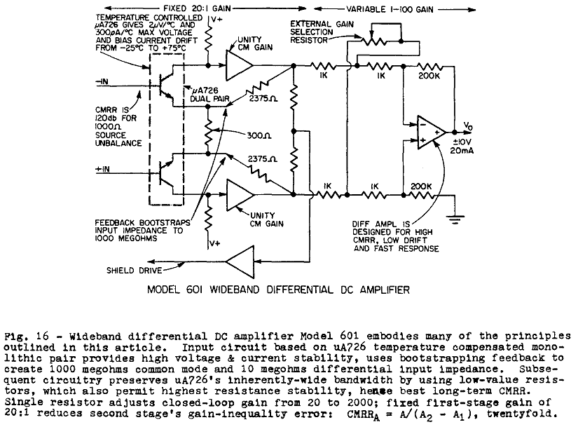
[quote author="Samuel Groner"]Robert Demrow, 1968. 10 years B.H. (Before Harris)

ADI_601.gif


From: Evolution_from_Op_Amp_to_Data_Amp.pdf

Now who's handling our history META? :grin:

Samuel[/quote]

Congratulations Samuel! I think that probably has to be the real goods on at least published priority.

I remember the uA726. Note that Demrow has a ~misstatement in the text block and in the linked text itself, although the inset with arrowed note on the schematic gets it right---it was distinctively a temperature-controlled chip. Note the power supply requirements on the last page! 601 got a serious heater!

One could quibble just a teensy bit about the undisclosed nature of the gain blocks, but clearly the idea is there.
 
Back
Top