Lurker works

GroupDIY Audio Forum

Help Support GroupDIY Audio Forum:

This site may earn a commission from merchant affiliate links, including eBay, Amazon, and others.

soundcollage

Well-known member
Joined
Dec 11, 2007
Messages
71
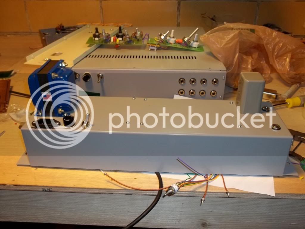
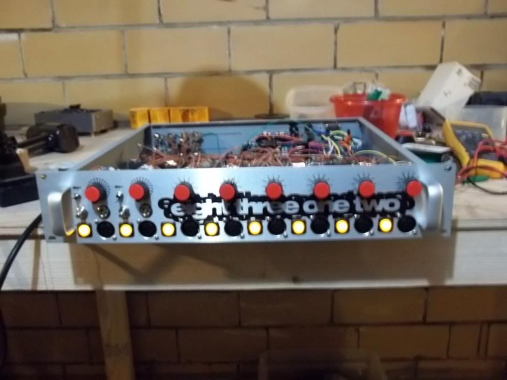
Greetings everyone, and thank you the wealth of information you have provided me with. I am an infrequent poster but i have been paging through everyone's posts for at least five years now. I finally have both a camera and a hosting account so I figured I'd post some photos of the projects you've unknowingly helped me complete. I just completed a marathon session of three simultaneous projects: an eight channel api 312, a silent arts dla2a, and a pultec peq/meq combo. I'll start with the 8312 in this post and add projects in subsequent posts so i don't get confused with too many links in a post. extra special thanks to classic api for the amazing parts.
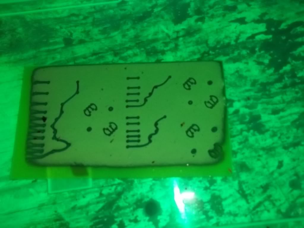
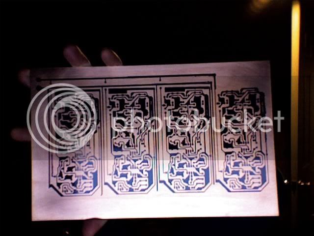
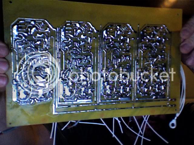
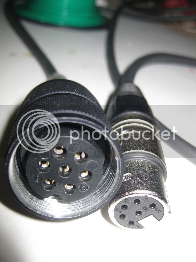
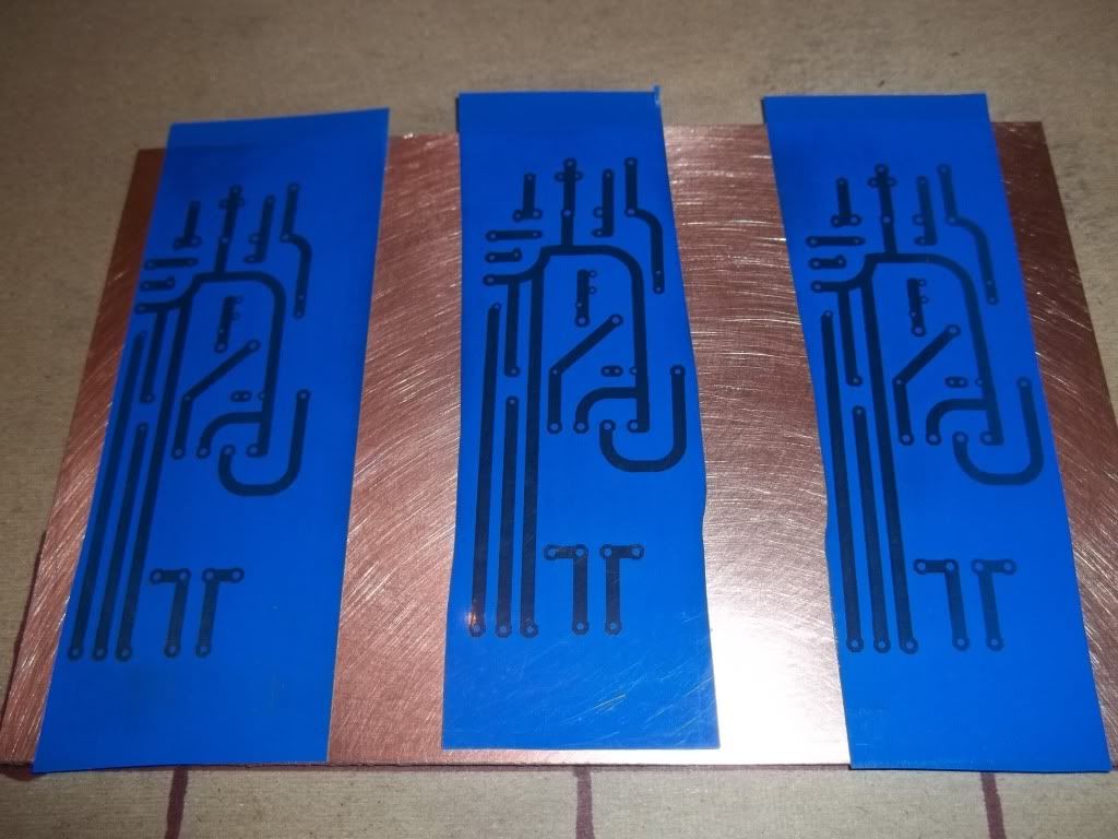
I designed my own boards for this- no phase or pad as I have specific reverse phase cables I made and in line pads if needed
000_0008-2.jpg

000_0007-2.jpg

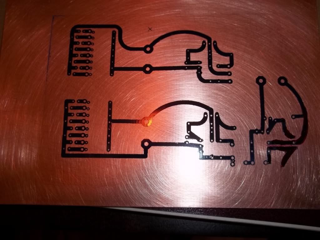
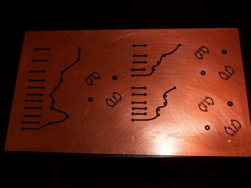
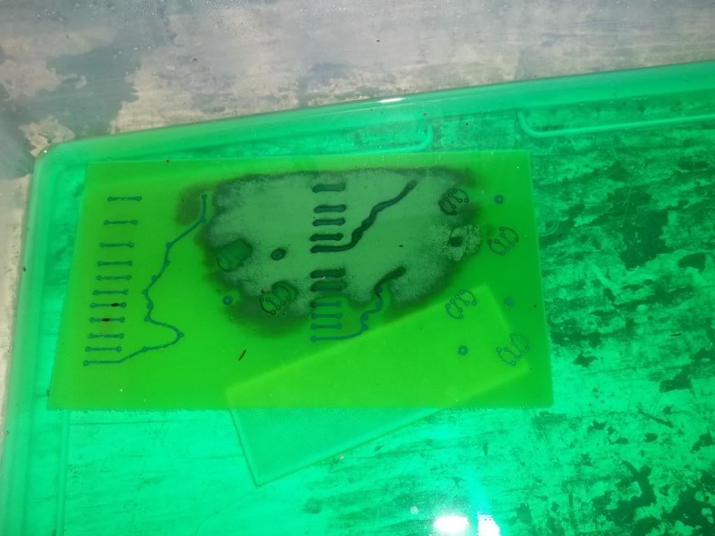
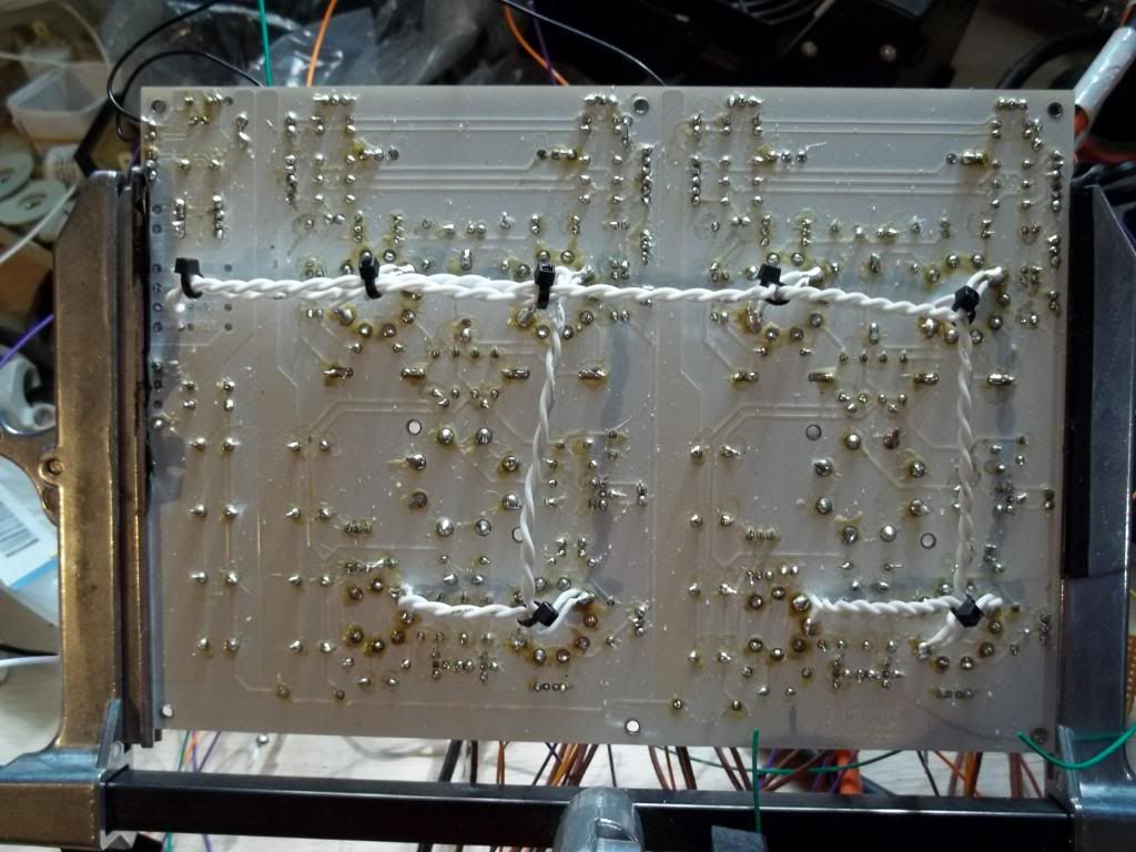
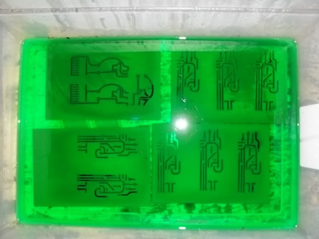
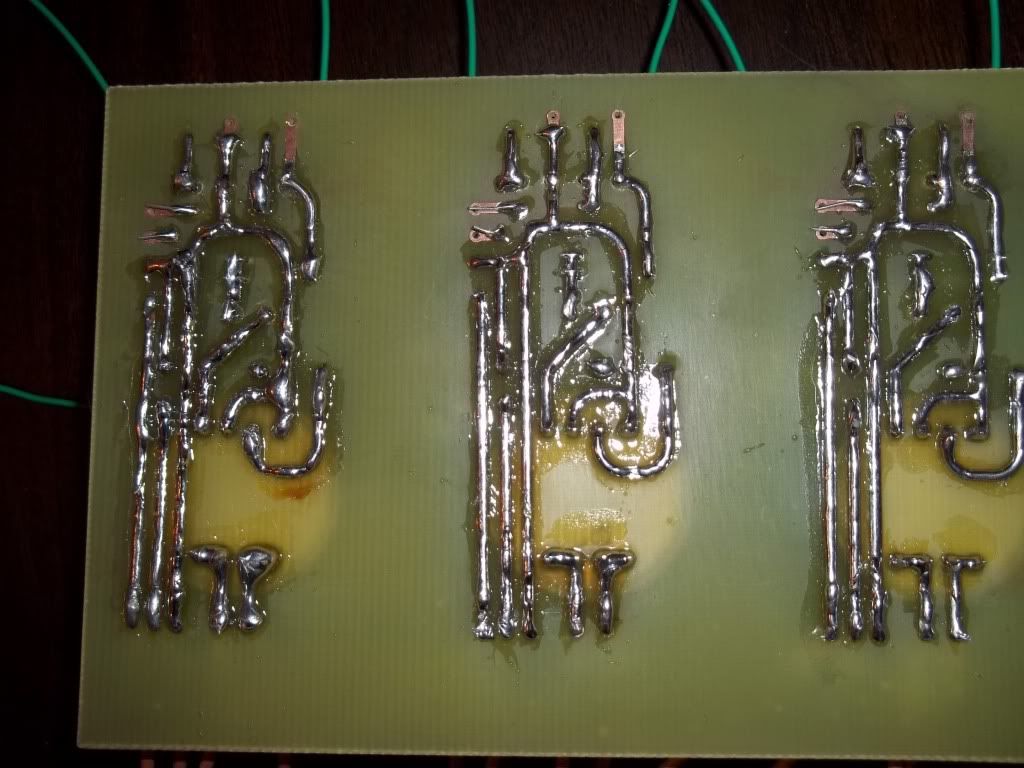
Into the cupric chloride, I grabbed the boards from the wrong pile so they were 3oz copper which i figured out after the 6 hour etch time.
000_0009-1.jpg

000_0001-9.jpg

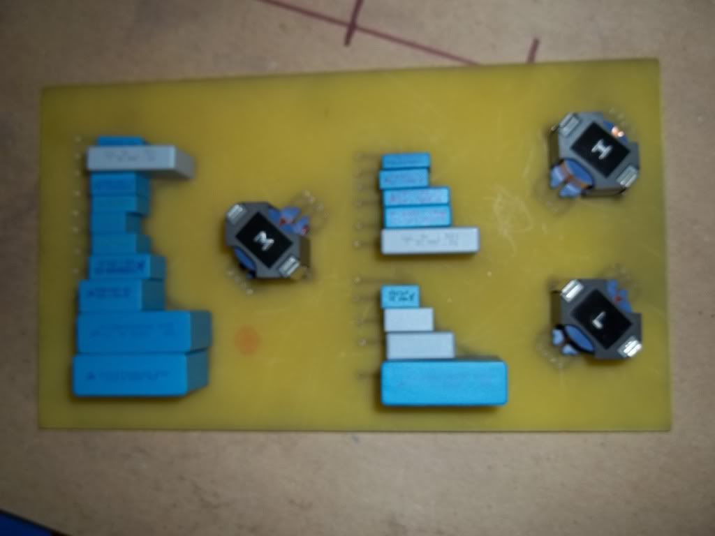
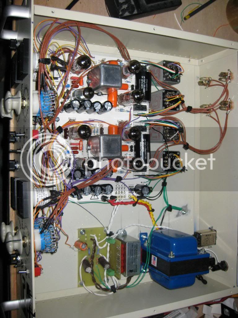
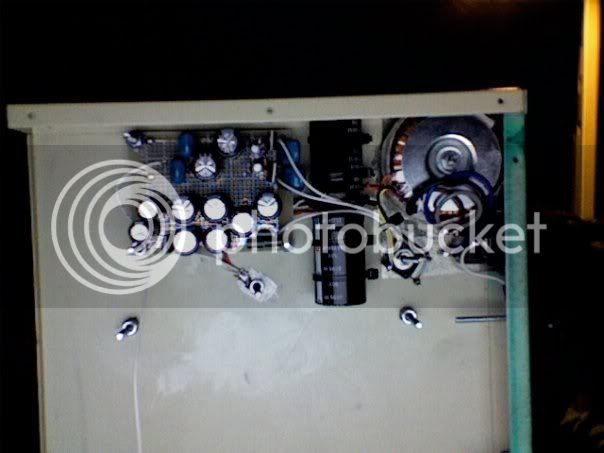
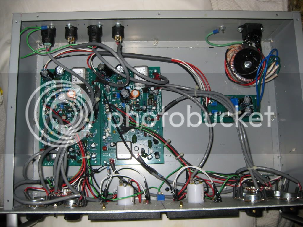
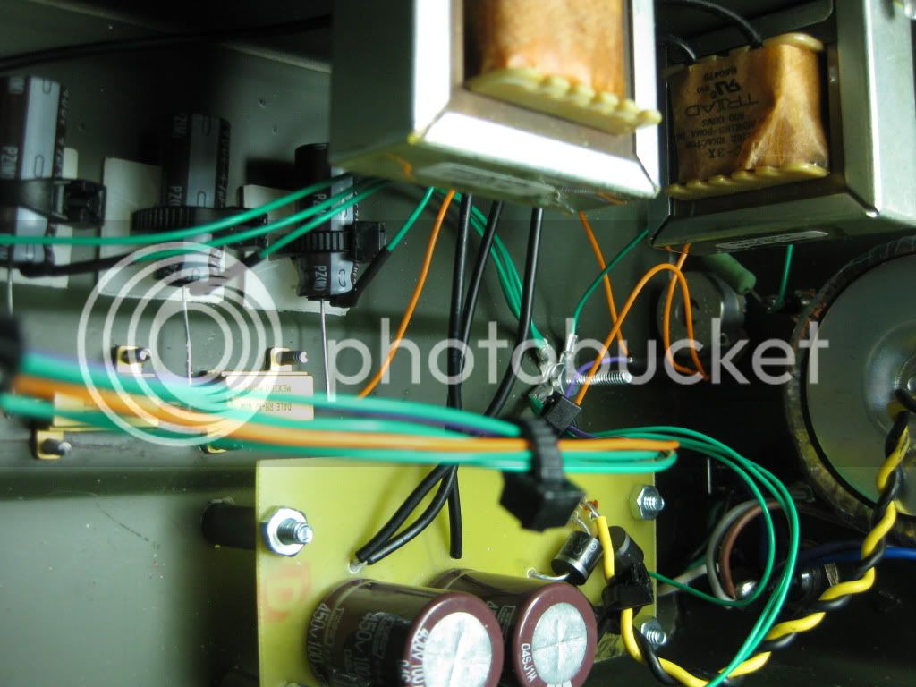
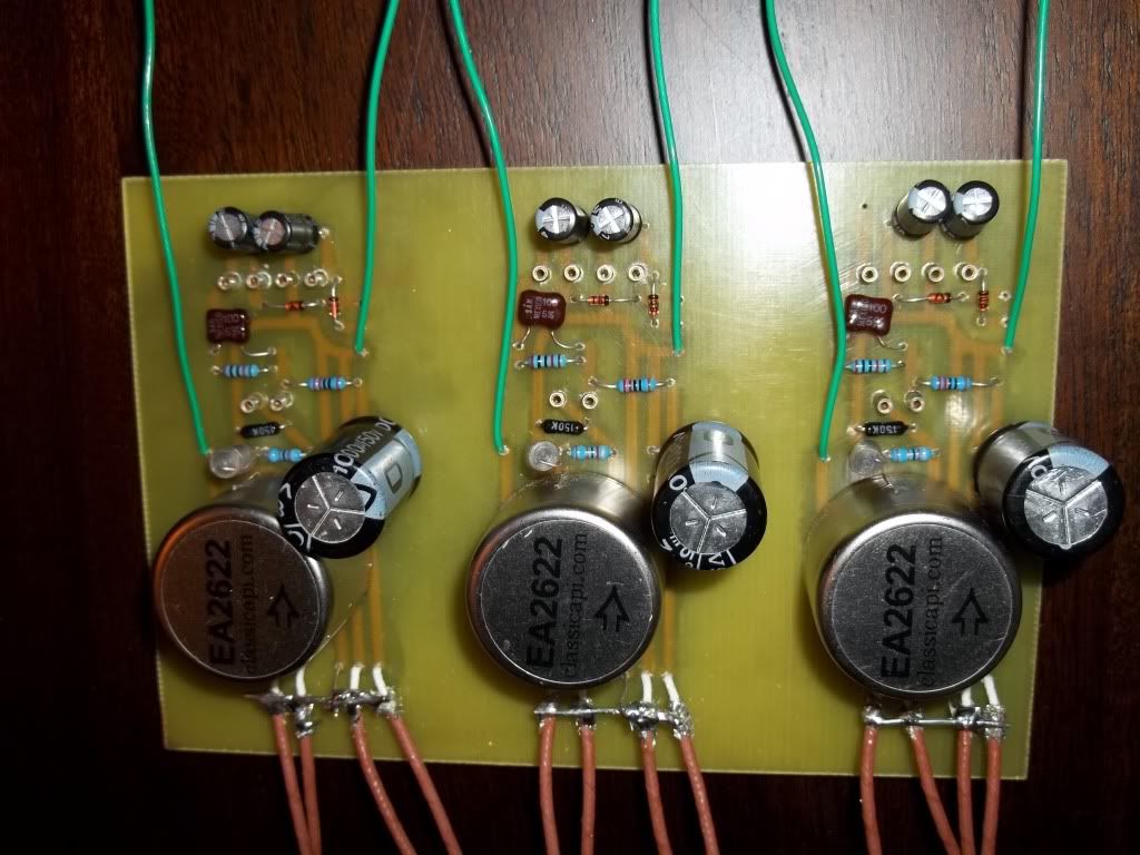
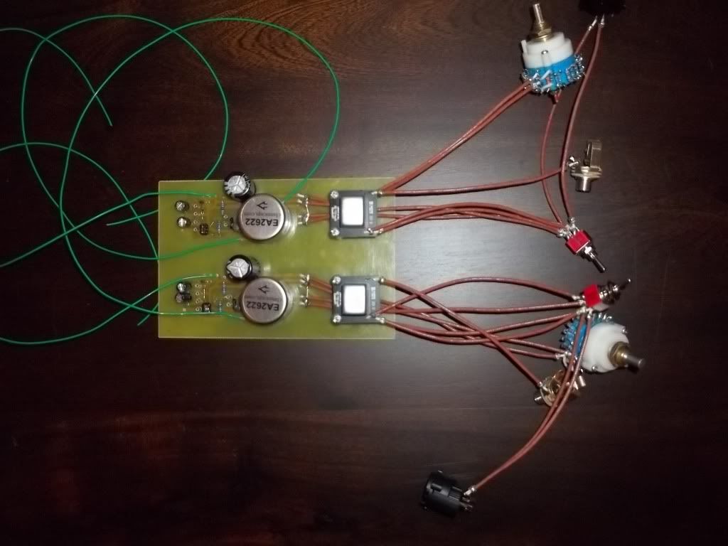
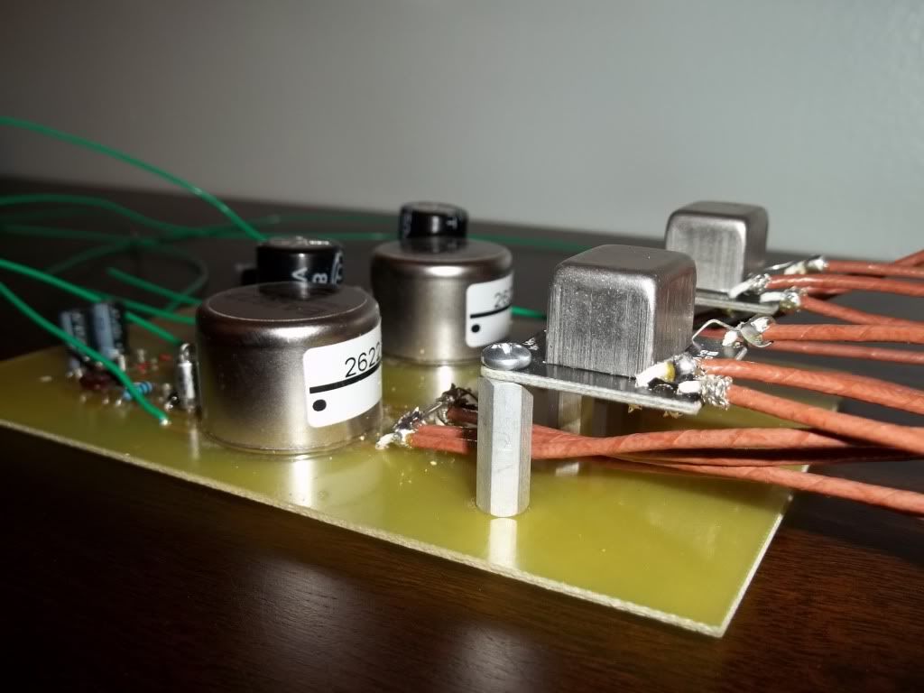
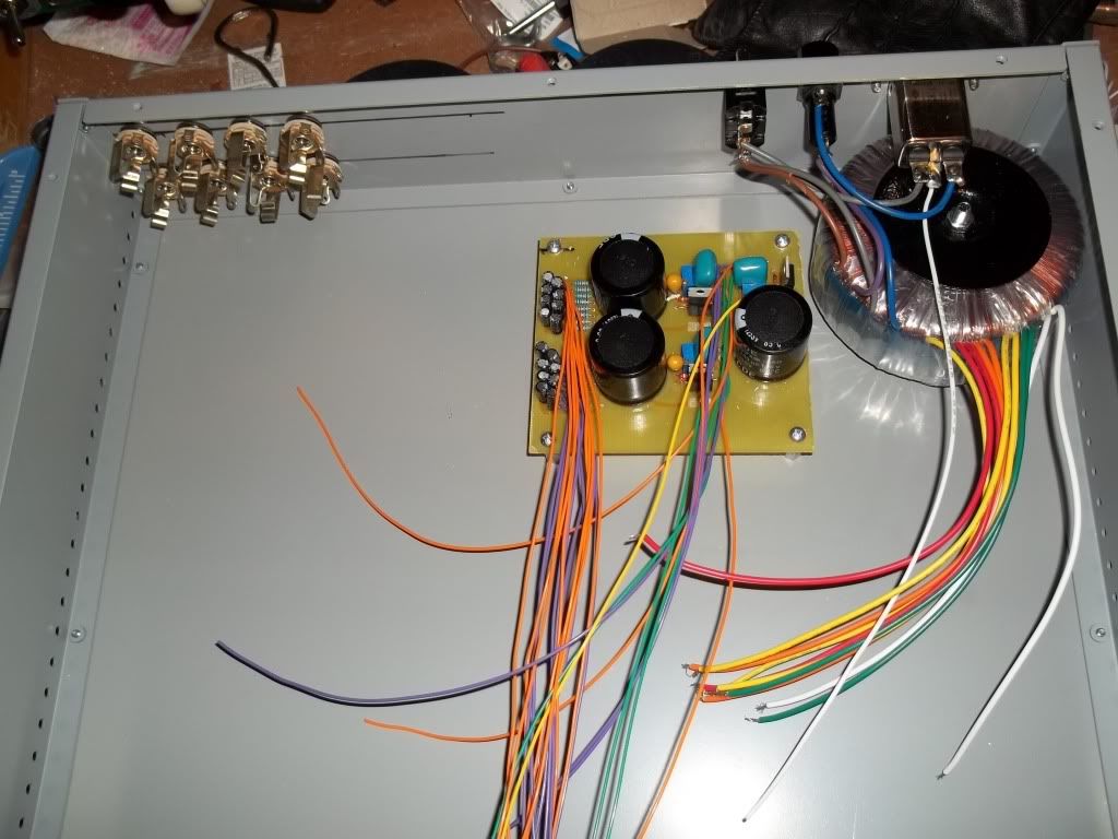
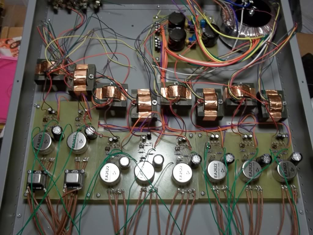
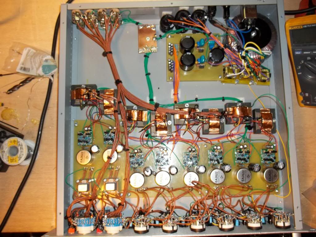
I worked off the gdiy 51x power supply schematic but 'isolated' each feed with its own 1k resistor/10µ cap.
000_0003-8.jpg

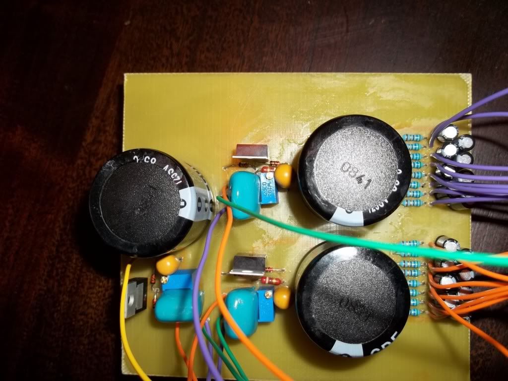
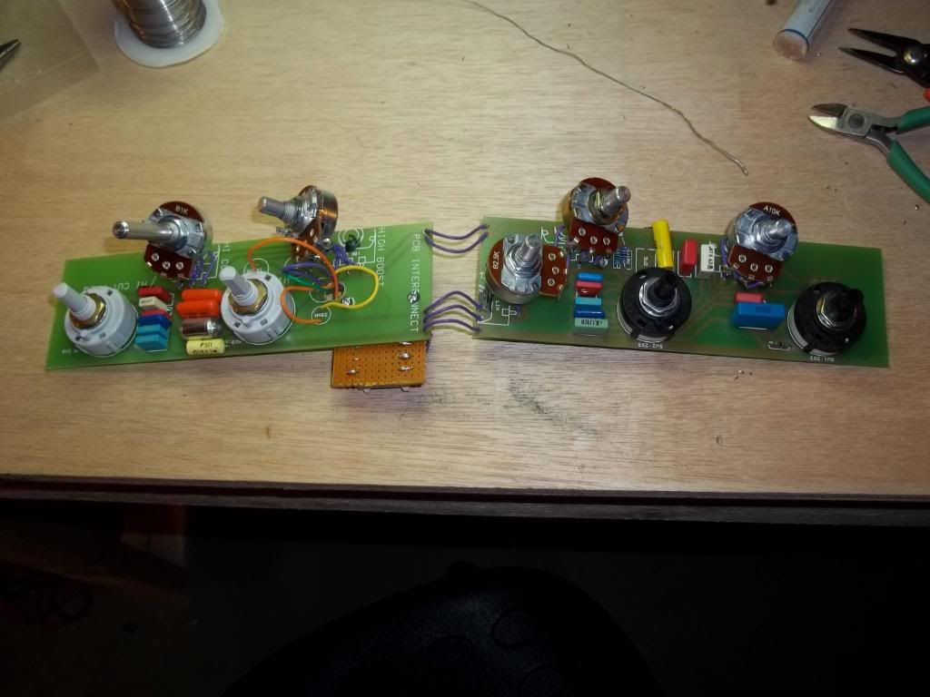
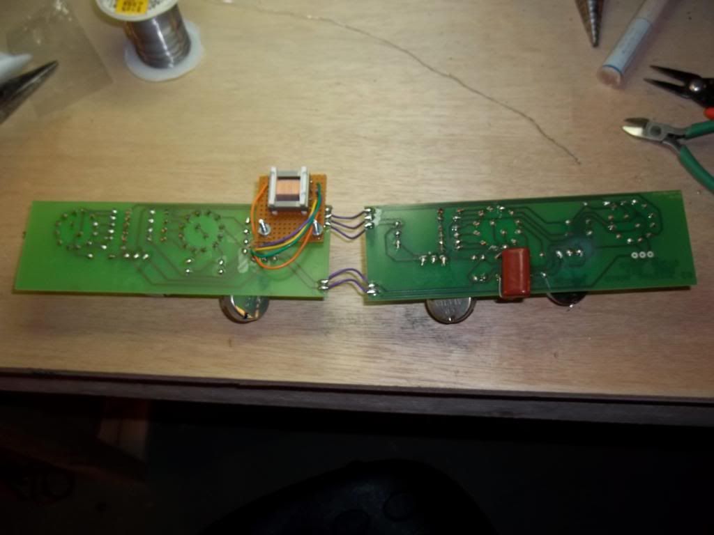
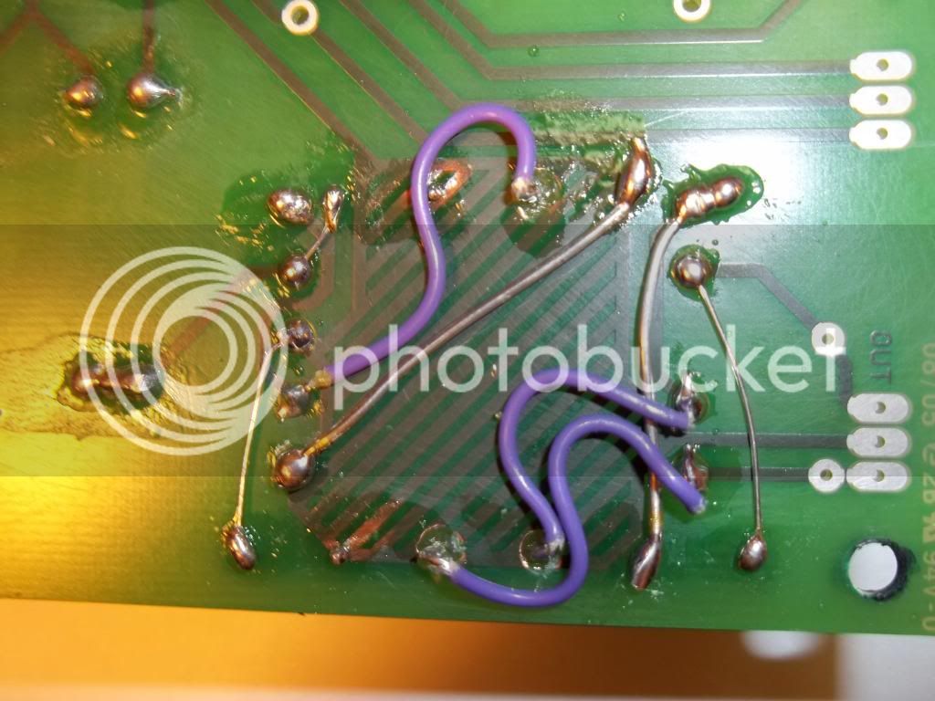
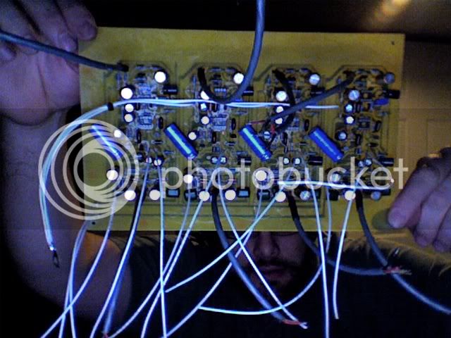
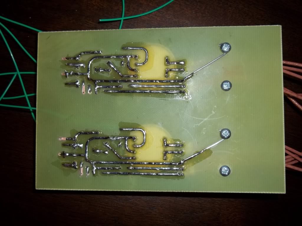
didn't check the size of the caps i had on hand before the layout so had to sneak a few in on the bottom
000_0004-4.jpg

000_0007-1.jpg

000_0003-7.jpg

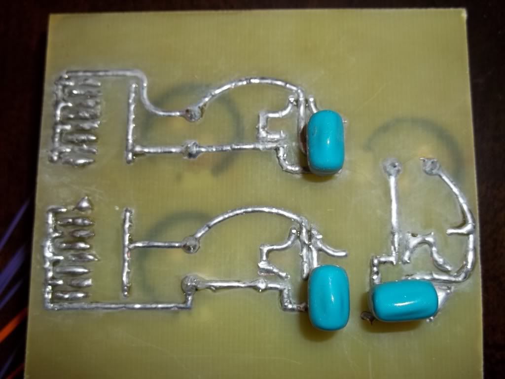
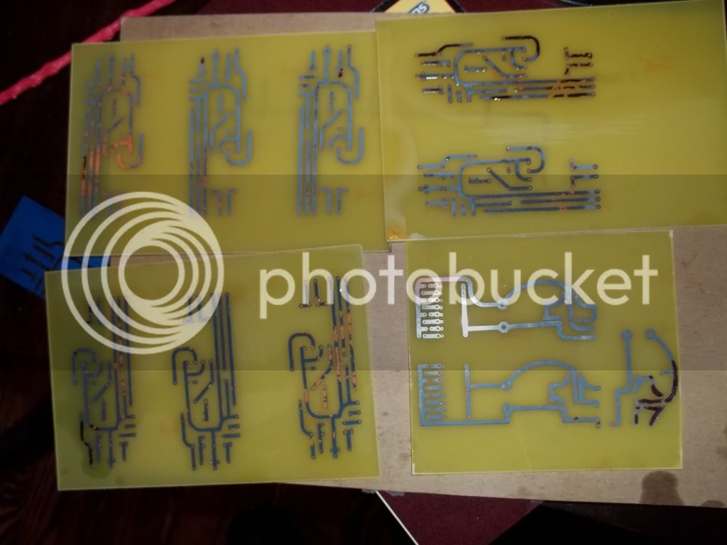
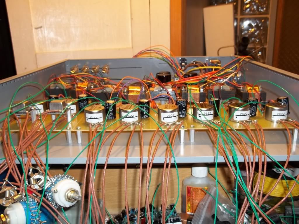
all traced end up tinned. with the 3oz copper these end up massive.
000_0008-1.jpg

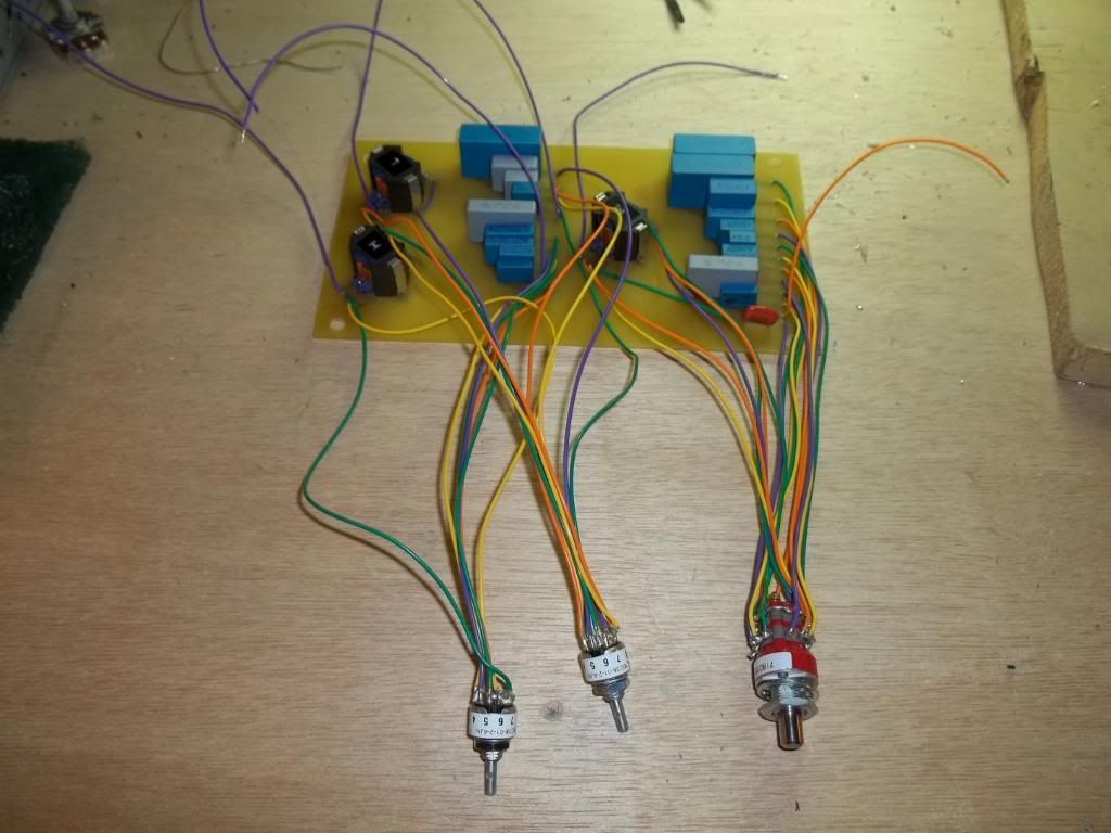
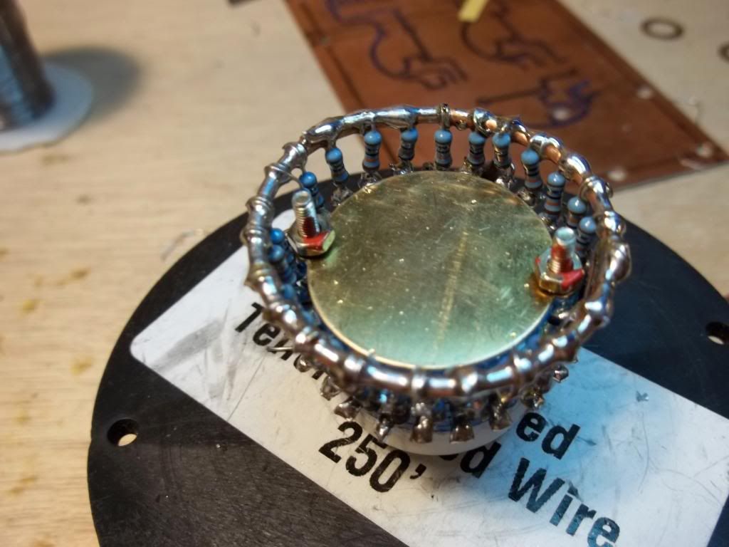
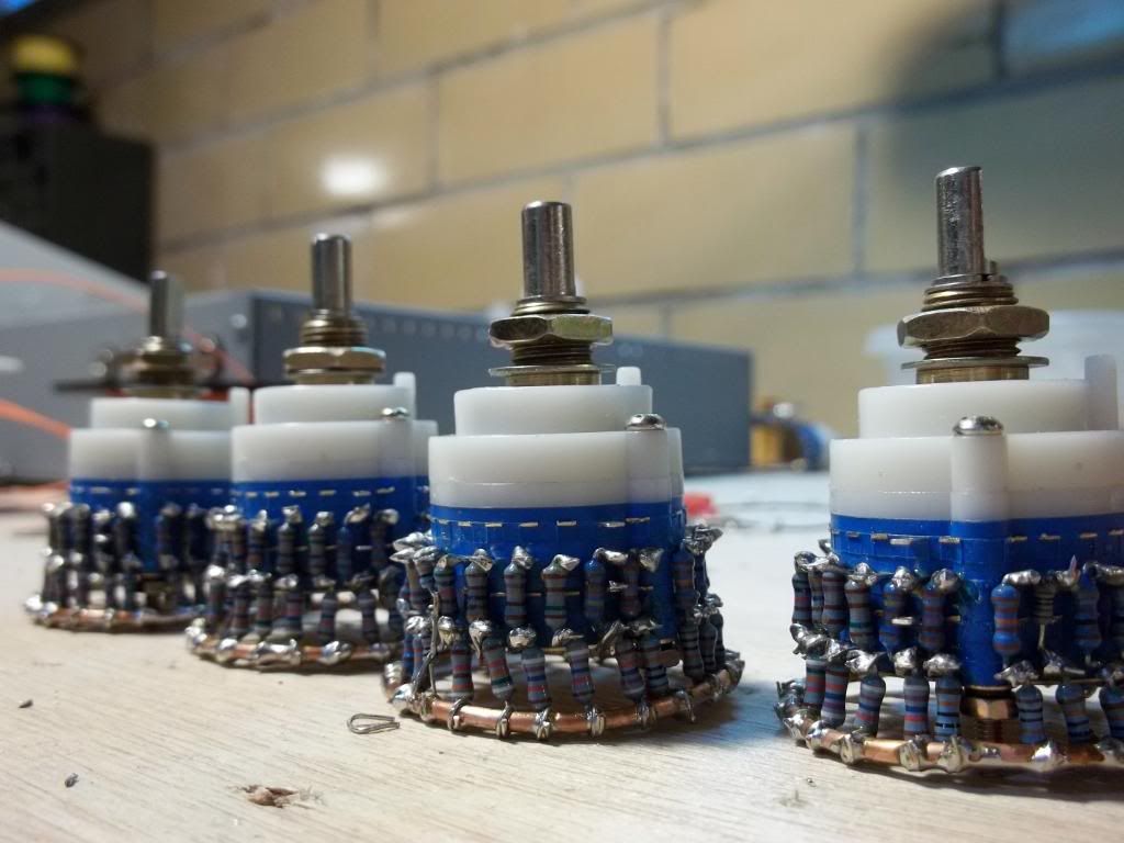
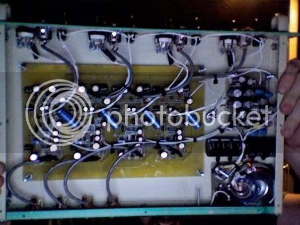
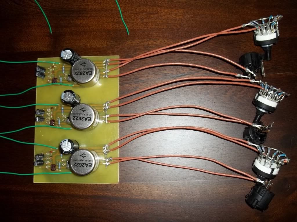
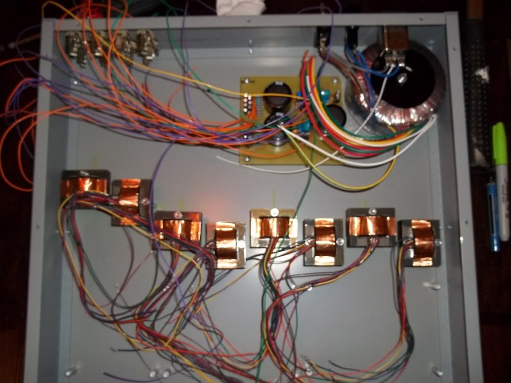
the first two channels have 24 pos gain switches, direct ins with pikatron transformers, and t-pad output attenuators.
000_0001-10.jpg

000_0002-11.jpg

000_0003-10.jpg

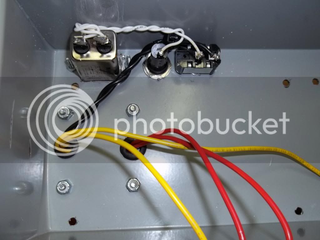
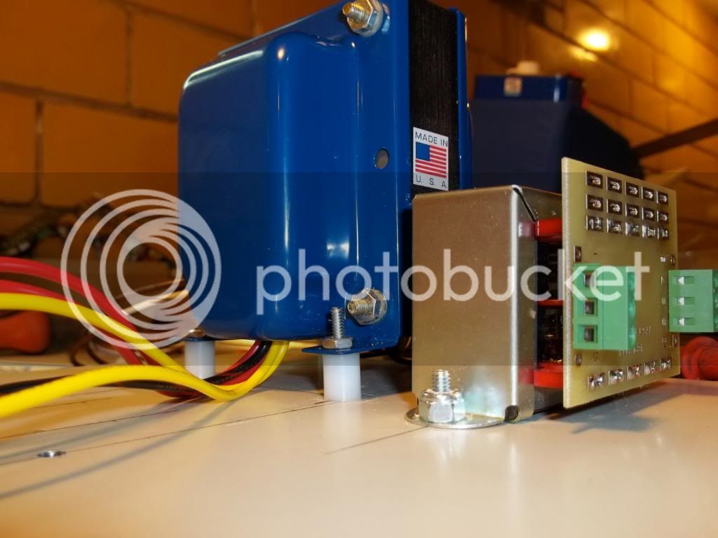
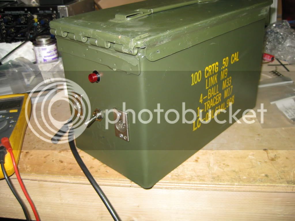
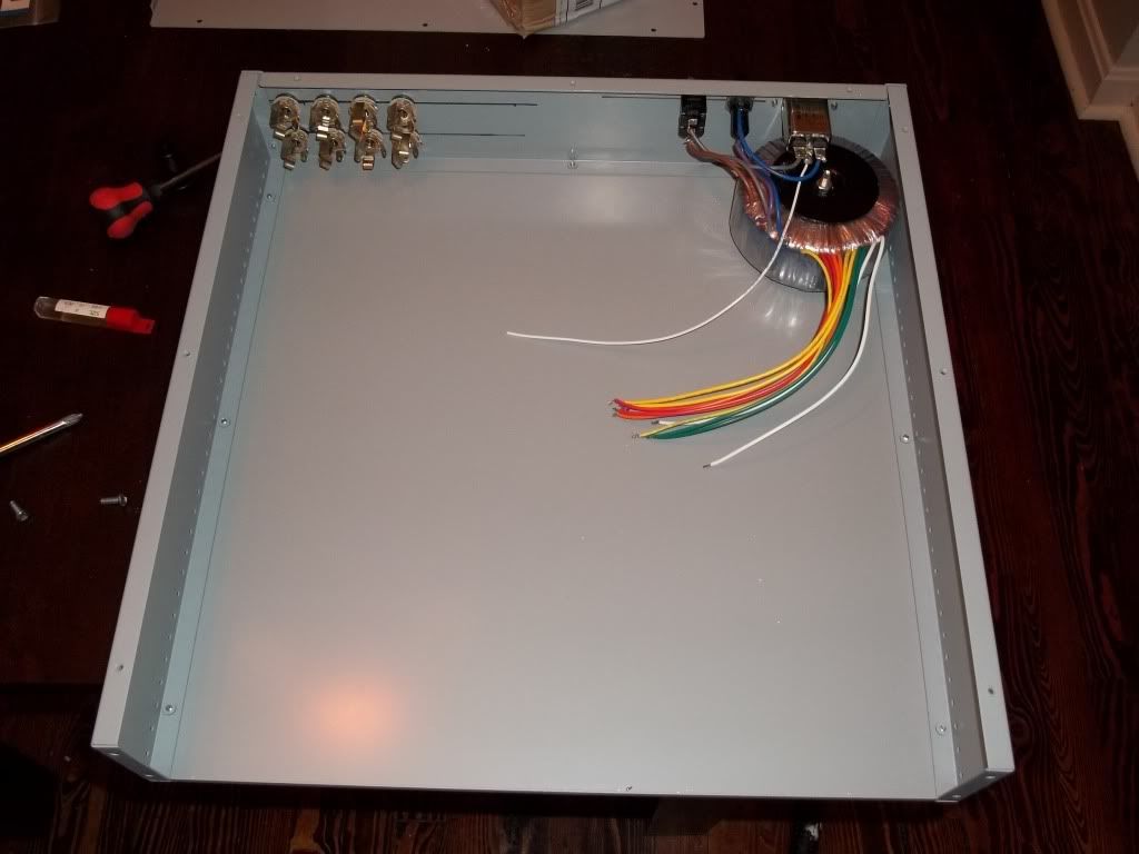
par metal case and gdiy toroid
000_00012-1.jpg

000_00022-1.jpg

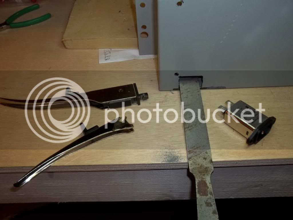
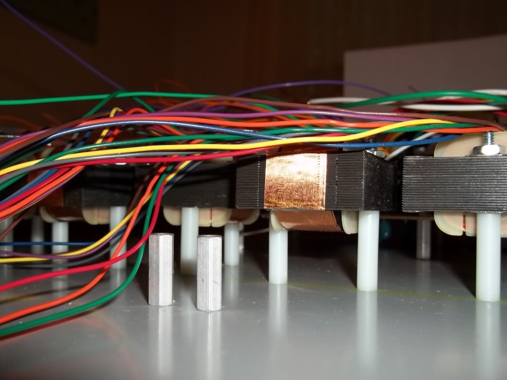
i have cutting square holes so i mounted the 2503's on standoffs
000_0003-5.jpg

000_0002-7.jpg

000_00022.jpg

000_00012.jpg

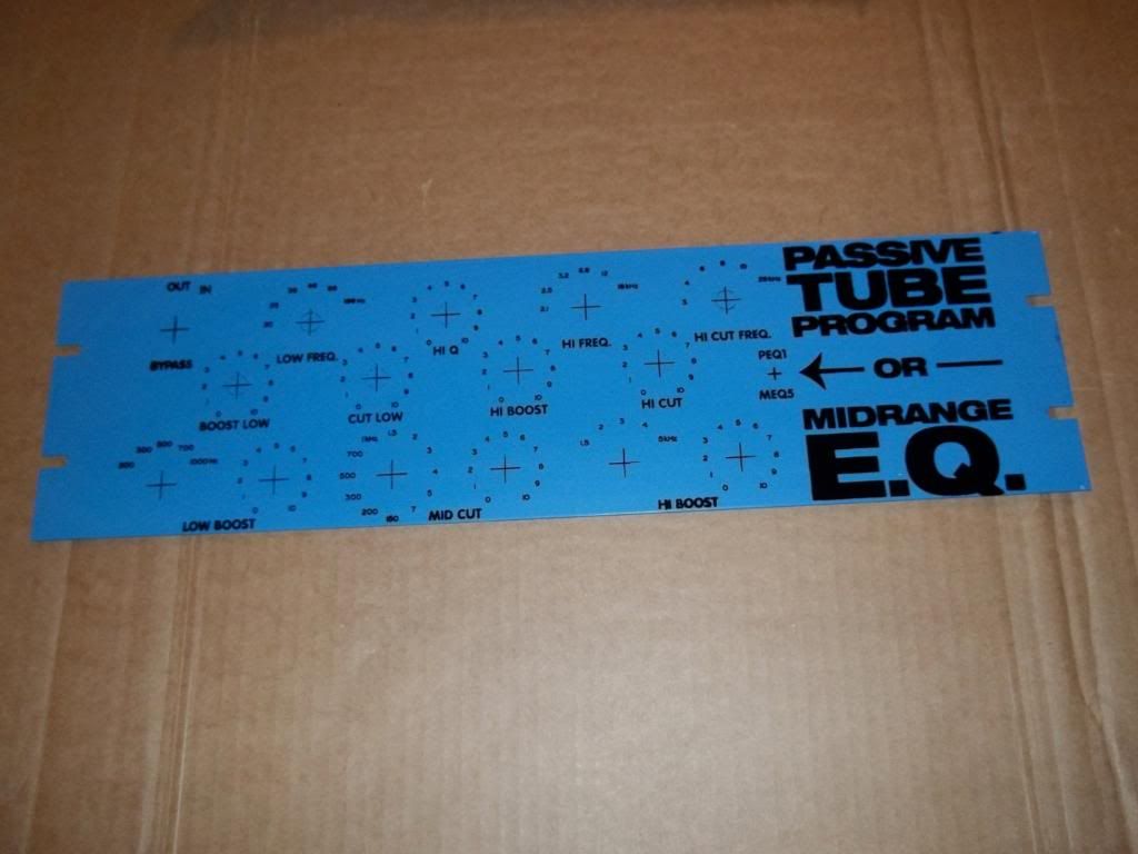
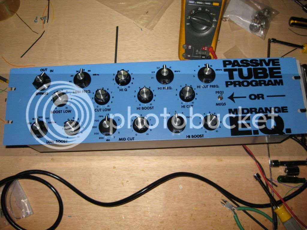
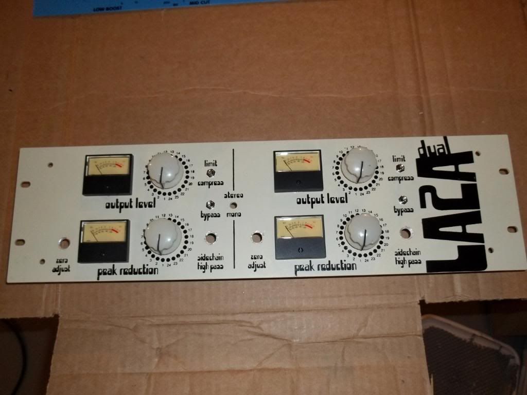
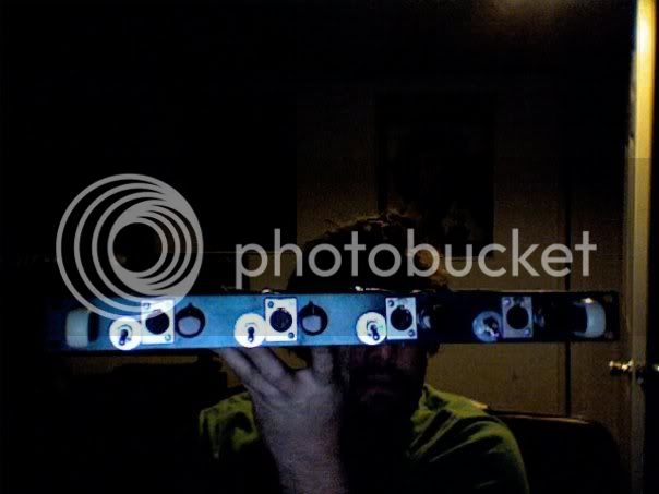
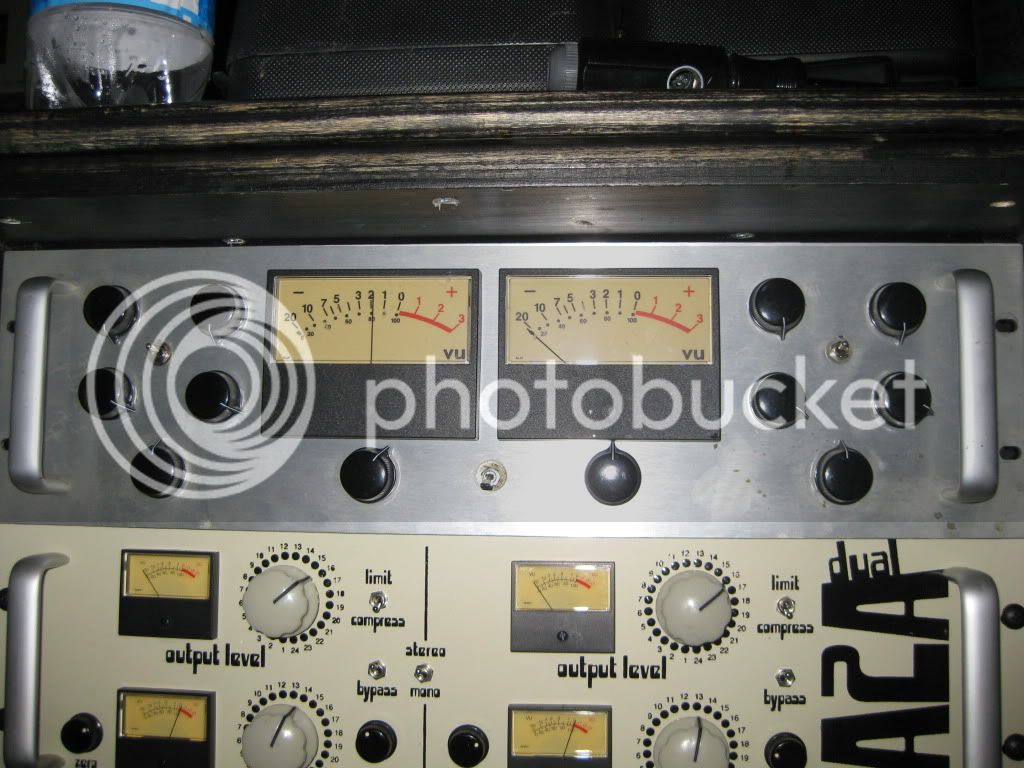
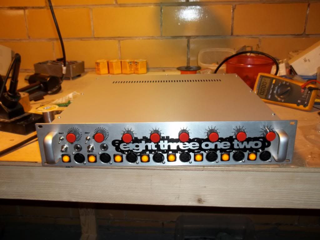
front panel silkscreened next to dla2a which i crammed on the same screen (I promised a silkscreen tutorial to someone, I'll get to that in a subsequent post in this thread)
100_0042.jpg

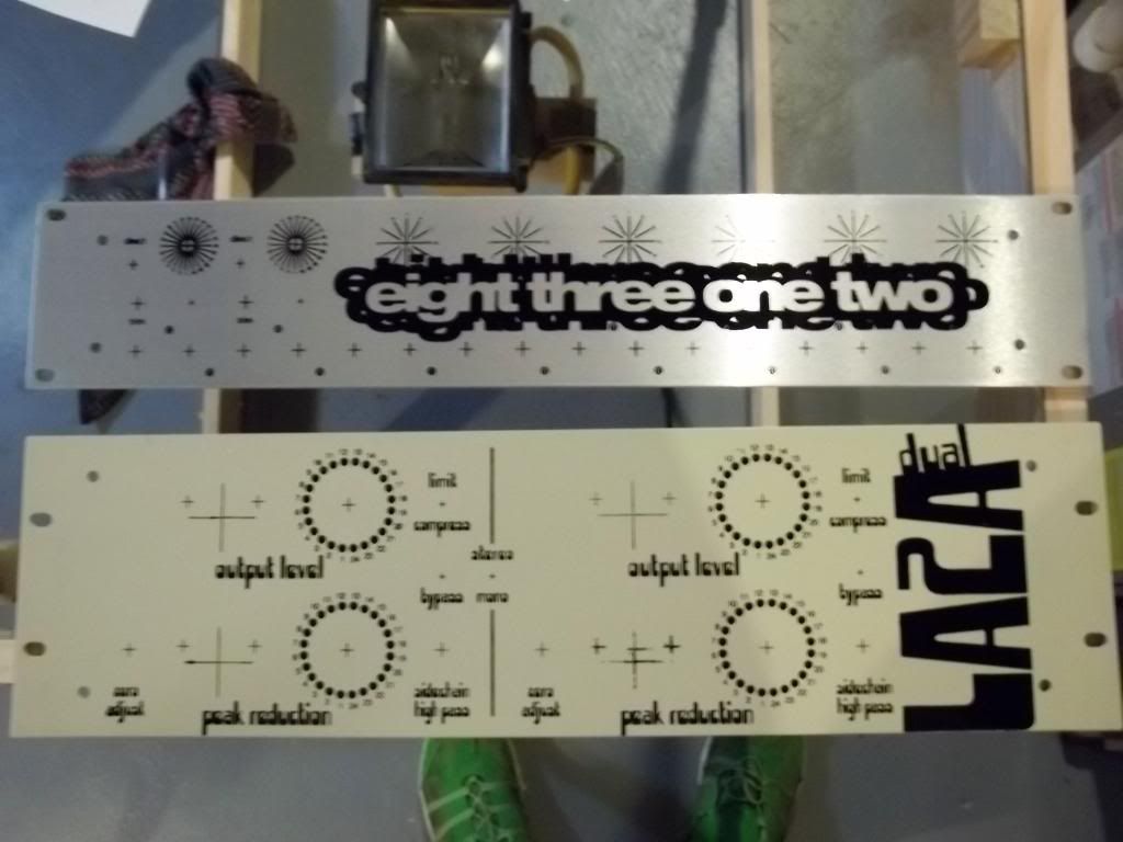
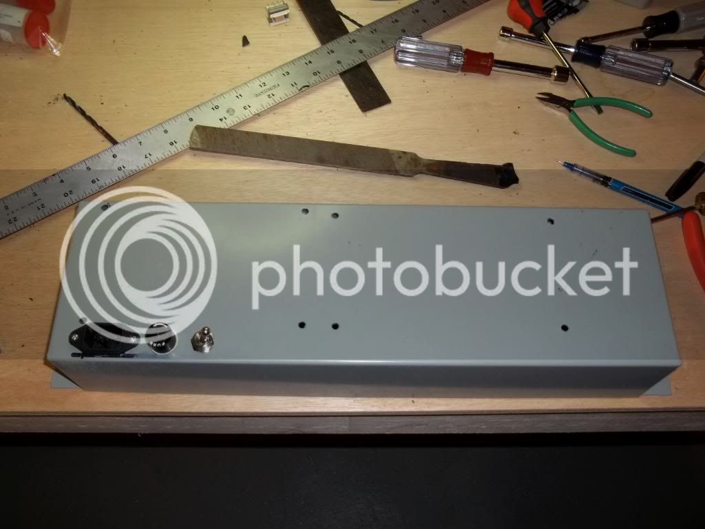
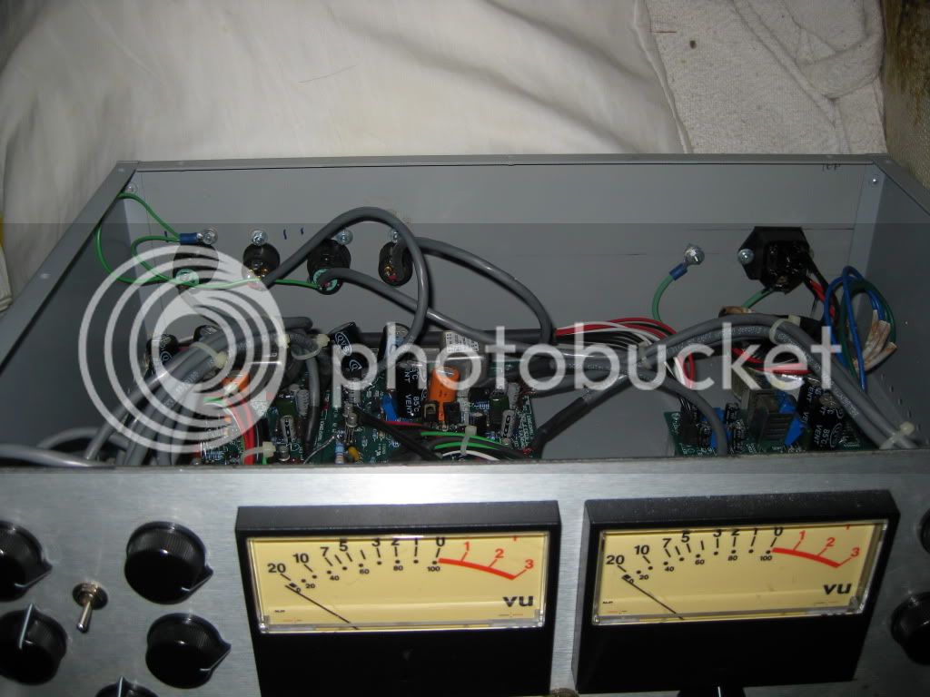
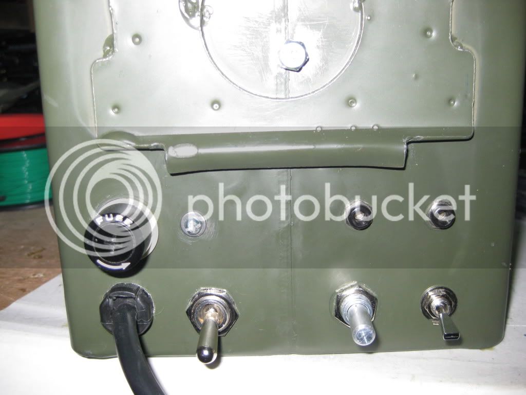
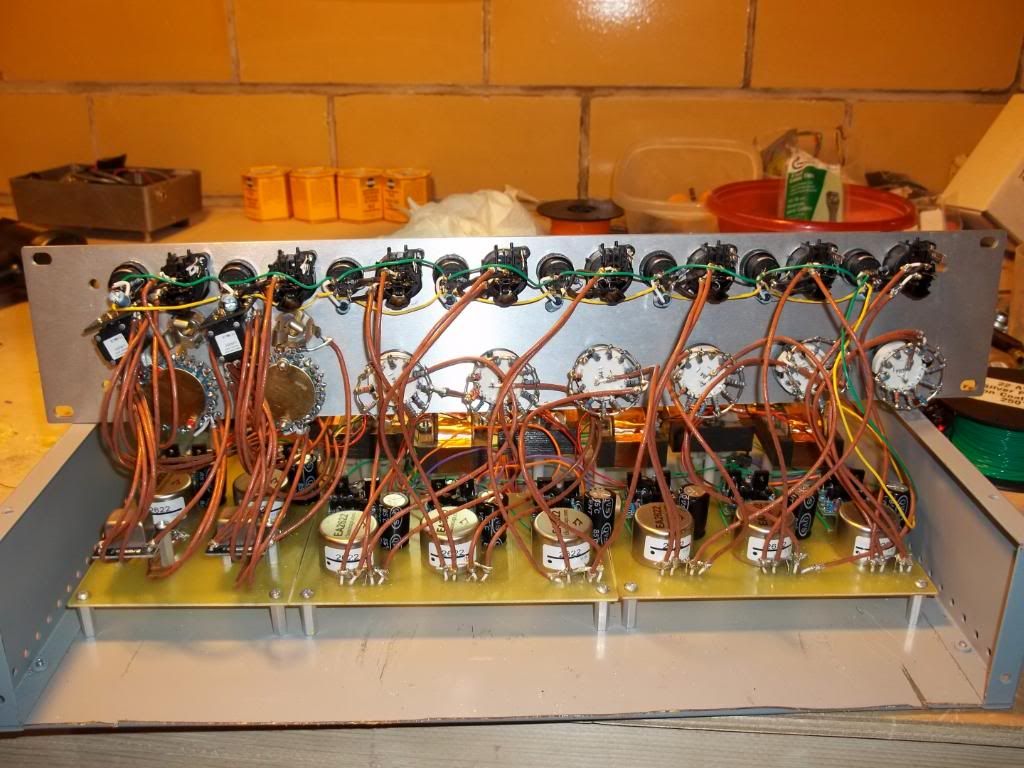
front panel drilled and illuminated phantom switched wired in. my only 'oops' in this project was forgetting about the front lip in the par metal case- i had to sawmill across the front to clear the xlr's
100_0048.jpg

100_0050.jpg

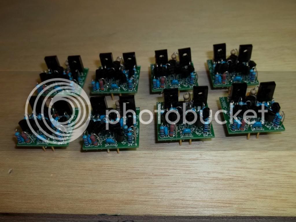
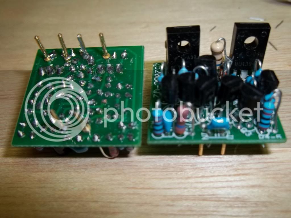
doa boards from classic api, but i sourced the parts myself only took 90 transistors to find 8 matching pairs
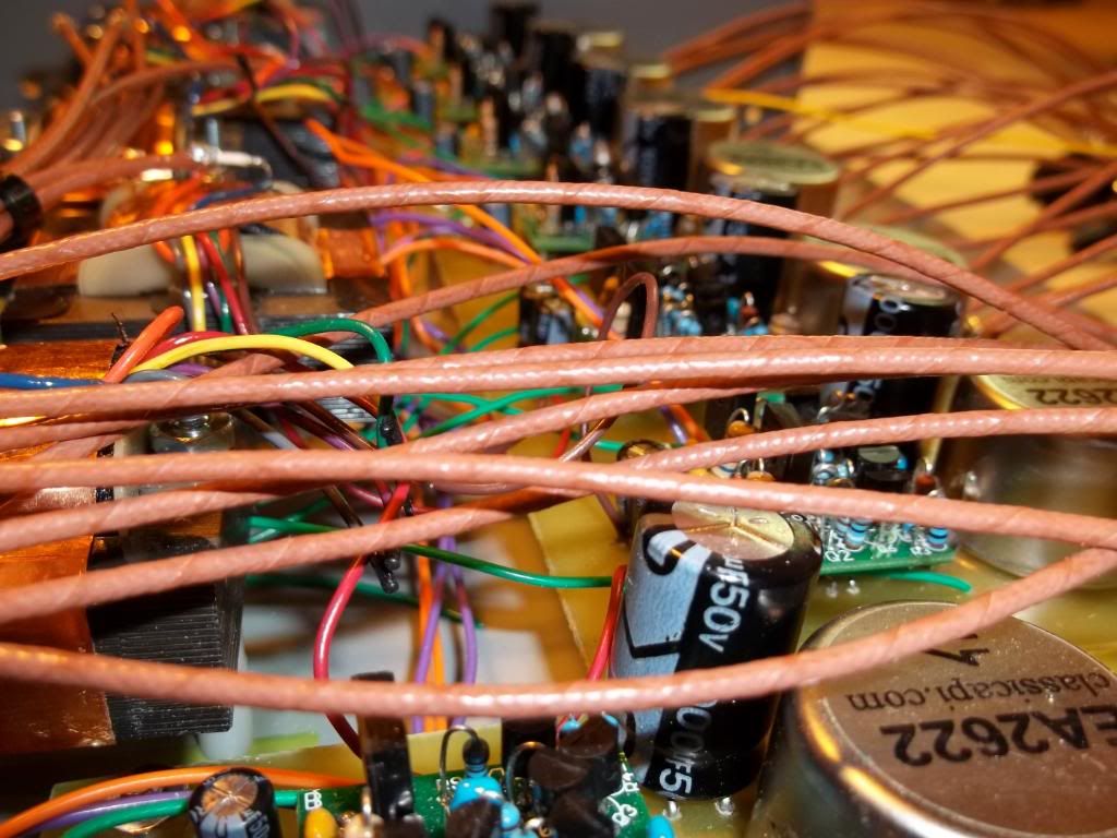
000_0002.jpg

000_0005.jpg

000_0011.jpg

tight fit
100_0055.jpg

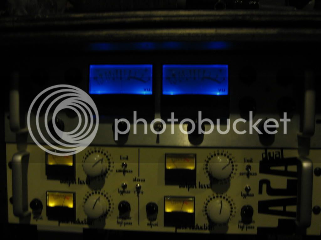
finished (I've since got smaller blue versions of the red knobs for the trim pots on the first two channels)
100_0057.jpg
 
Thanks to Nielsk for the peq boards and chassis,  and ChrioN  for the top quality inductors.

000_0001-2.jpg

000_0002-2.jpg

for the meq section i poked the capacitors through a piece of paper into foam- since the wimas have very specific lead spacing, then scanned the paper, connected the dots and added the pads for the inductors
ll001.jpg

p'n'p ironed on
000_0002-12.jpg

etching
000_0003-9.jpg

000_0005-4.jpg

drilled/filled
000_0001-11.jpg

please note the dots on gyraf's meq schematic are the fully clockwise position, not position one. i had to rewire these switches- hopefully this saves someone else that trouble.
000_0002-3.jpg

the chassis i got from nielsk was super thick! i squeezed the handle right off my nibbler and had to finish with a file.
000_0001-1.jpg

000_0003-1.jpg

000_0001-4.jpg

i did not have the height for the decor adapter board, so i drilled right into the board and jumpered  the pins to their appropriate location. a few pins went through the ground plane so i took a larger bit and scraped away the copper.
000_0002-4.jpg

the triad input transformer got mounted on the outside near the input.
000_0004-2.jpg

faceplate spray painted and screened
100_0045.jpg

crazy tight fit
IMG_0002-1.jpg

tube exactly even with faceplate
IMG_0006.jpg

finished
IMG_0007.jpg

 
thanks to silent arts for the great board, and hairball for the affordable meters.
000_0002-6.jpg

dry fit of parts
000_0006.jpg

i originally made boards to mount these on so you could see the cool UTC logos on top but they ended up looking sloppy so i used the holes in the top.
000_0007.jpg

decor power transformers the second is for the heaters on the right channel since there was only one winding on this transformer
000_0004-3.jpg

went with 24p switches in the ladder configuration for these
100_0014.jpg

100_0015.jpg

heater wiring
100_0043.jpg

the extra board is to elevate the heaters to 60v dc (a habit i got into building guitar amps) i also had to steal power for the meter illumination because the 5v relay line would not turn on the hairball led's
IMG_0003.jpg

stuffed faceplate
100_0046.jpg

finished
IMG_0004.jpg
 
here's my four channel v1 green once again no phase or pad.
this is before i had a camera so they are all imac photobooth shots
here is the p'n'p on the copper clad board. pretty sure i just used the v1 layout but added the power rails on the board.
Photo248.jpg

Photo266.jpg

Photo267.jpg

i did the powersupply on pad per hole perf i cant remember what schematic i went off of.
http://i1119.photobucket.com/albums/k632/James_Welding/n1410014271_328946_4463901.jpg[/IMG
[IMG]http://i1119.photobucket.com/albums/k632/James_Welding/n1410014271_328948_2474127.jpg
n1410014271_328949_3141225.jpg

n1410014271_328950_1763978.jpg

n1410014271_328951_1499102.jpg

this is also before i made the switch to teflon wire and a thermal stripper (highly recomended)
i used comically overrated carling switches for the phantom.
 
here's my dual 1176
IMG_0542.jpg

gigantic meters
IMG_0543.jpg

unlabeled- this is before i got my wife the silkscreening setup. i included a transformer/ electric balance input switch on each and the nuke mod on the rotary ratio.
IMG_0002-2.jpg

lights on
IMG_0003-2.jpg
 
ok, I was asked about the silkscreening process in the DLA2A thread, so here's a brief walkthrough. we have a fairly elaborate set up including a four color press here, but i'll go into how to accomplish quality results with the least amount of equipment.
first find a silk screen supply company in your country. almost every place that sells screens on frames also  sells them with the emulsion pre-applied.
they will send it to you in a light safe bag. get a 200 mesh screen unless you have a ton of fine detail in your design then get 300 mesh.
you will also need a squeegee from the same company if you're only making one faceplate you can skip getting all the cleaning chemicals and just throw the screen and frame away when your done. nazdar 59000 ink is the best for application to anodized aluminum or powdercoating if you're lucky the silkscreen supply company has it, if not source it somewhere else. if you end up using a 300 mesh screen you will need to get some nazdar ink thinner too as its pretty thick .
go to a hardware store and get a 500w halogen worklight  and take off the UV filtering glass. also pickup a yellow 'bug' lightbulb.
work up the artwork in any design program and print it onto a transparency as darkly as possible in black ink either at home or at a photocopy place. the final faceplate image does not have to be black this is just to create the stencil on the photosensitive emulsion.
rig up a way to suspend the halogen worklight about 16 inches above a platform that will fit the screen frame either with pvc pipes or scrap wood and duct tape. or i guess you could hold it it if you have super steady hands and uv eye protection.
go somewhere dark  where the only light source is the yellow bulb you bought.
take the screen out of the light safe bag and put it so the screen is on the top (not the frame) tape the transparency in the center of the emulsion make sure the ink on the transparency is touching the emulsion (and the image is reversed) if you happen to have some plate glass its a good idea to squish the transparency to the screen with the glass so no light cant get around the black ink but it will work without it.
place the screen frame under the halogen light and turn it on for about 13 minutes.
turn off the light, take the transparency off the screen and put it back into the lightsafe bag. wait till its dark outside and use a hose with a nozzle set to stream. first wet both sides and wait a minute. then blast the image with the hose from the side where the image is reversed. the areas where the light was blocked will wash out of the screen.  if need be this can be done in dark bathroom shower with a little coaxing from an old toothbrush but the results won't be as good.
after the image is washed out let the screen dry then either put it back under the halogen light or in the sun to harden more.
i forgot to mention registration marks but  make sure you add some to the artwork to help align the image on the faceplate. put some scotch tape over the marks so ink does not go through but you can still see them.
find a flat area bigger than the screen frame to work on -a place you can make a mess on.
use double sided tape to fix the faceplate to the flat surface
tape a stack of two or three coins to the bottom corners of the screen frame depending of the thickness of the faceplate. you need the screen to be about the width of one u.s. quarter higher than the faceplates so the screen springs off  after the ink is squegeed on. 
you need helper now because the screen needs to be taped in place when its aligned over the faceplate it cant move or the image will get messed up.
triple check that its aligned and nothing is able to move then apply the ink in a line on the opposite side of the image from you. very gently drag ink over the stencil to fill in the area washed out of the emulsion don't push hard enough to touch the faceplate (this is called flooding the screen) then make a pass pushing down hard and steady with the squeegee at about a 45deg angle. this pushes the ink through to the faceplate and as you drag the screen snaps up and away if you've spaced it right.
pull off the screen and put the faceplate somewhere it won't get touched or dusty as the ink takes a longtime to dry. wait at least 48 hours to drill or you will smear the ink or get metal flakes stuck in the ink.
there are all kinds of extra purchases that will make each step easier but that is the minimum amount of equipment needed to do this.
nazdar cleans up while its wet with xylene (which smells like 1970's magic markers) but its pretty nasty stuff so wear gloves.
 
Thank you a lot for going through the process. Armed with your keywords I have searched a bit on youtube and now have a lot to digest and think over :)

your stuff looks great :)
 
Very nice mic build!

Just a tip, though - you might want to reverse the gender of the mic connector on your PSU there. You'll see why when you get your first belt off the B+ pin.  ;)

 
Yes, I'm aware of the shocking potential, but 105v is not terrible and it would be nearly impossible to get it to arc across my heart as the ground pin is directly adjacent. The male jacks were much cheaper and the cord was annoying enough to solder that I'll take the inevitable cooked fingertip if I eventually get careless and I'm sure that will motivate me to be careful again for a good bit of time. Plus, the only time I would power It up with out a mic plugged in is in the unlikely event It leaves my studio to make sure the voltage is not crazily out of spec. Thank you for looking out though, and it's good advice for people building a power supply that someone else will be operating.
 
Back
Top