khstudio
Well-known member
Just curious... How do these compare (Component & sound wise) to the 2520's from the GROUP Buy?
I have the second batch that aren't potted.
Thanks.
I have the second batch that aren't potted.
Thanks.


 [/quote]
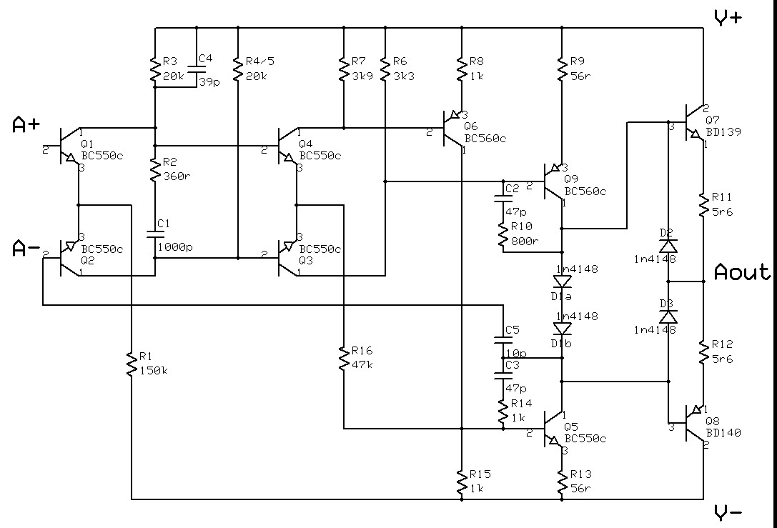
C1 - 1000p
C2 - 47p
C3 - 47p
C4 - 39p
C5 - 10p
CD1 - 100n
CD2 - 100n
D1a - 1N4148
D1b - 1N4148
D2 - 1N4148
D3 - 1N4148
Q1, Q2 - BC550, matched
Q3, Q4, Q5 - BC550
Q6 - BC560
Q7 - BD139
Q8 - BD140
Q9 - BC560
R1 - 150K
R2 - 360R
R3 - 20k
R4 + R5 - 20k
R6 - 3K3
R7 - 3k9
R8 - 1K
R9 - 56R
R10 - 800R
R11, R12 - 5R6
R13 - 56R
R14 - 1K
R15 - 1K
R16 - 47K
Enter your email address to join: