prr varimu compressor

GroupDIY Audio Forum

Help Support GroupDIY Audio Forum:

This site may earn a commission from merchant affiliate links, including eBay, Amazon, and others.
You used KENT's board layout?
the Rs on PRR's schematic are probably test points to look at sidechain action (cause his schematic is from a simulator)
but you will notice that the R's also correspond to the points where KENT does some linking in the sidechain since his piece is in stereo.  I used a rotary switch for attack and release controls so I didn't need to link for that, but I did link/sum at one of the R's to get my meter to indicate in a useful way.
K
 
so i got it working...
sounds great! very clean!...seems odd to only have about 40vdc on the tube plates though..

i was reading back over prr's page on the comp over some coffee over and over and then i tried something...and that was the problem!

the compression amount is based on the input amount....
my card was not putting out a hot enough signal to do much....
went out from my card, into my headphone/monitor controller-amp...into the unit then out to my speakers for a test and no problem!

::)

now i need to build a line stage on the front end of it with variable volume!
 
http://1176neve.tripod.com/id6.html

that should actually boost the signal well yeah?
could make a dual version and use that on the front end...
i am wondering if i need a input transformer if i put in a opamp based line amp in front of the tube...

also, are the 6bc8 really better sounding and acting in this unit then the 12au7?
i have some 6bz7's which are the same and plenty of trannies to put the 6vdc for those filaments.

also...i will probally make both sides functional this weekend...
i will probally use pots rather then rotary switches.
there is no cross talk between channels if i put the connectors from both on the same single pots is there?
i have dual pots i could use as well..
 
right now my card outputs unbalanced only...
the balancing amp should work good for my purposes as a general boost in front, plus i can put a pot somewhere where it outputs to feed into the comressor. That would work as sort of a ratio as well as the ratio is controlled by the input amount.
i could get a new card  ;)
but i only have 6 weeks before i move and start service. just trying to record a few tracks and have fun mastering some old stuff i have better before i leave.
i was looking around for a simple bc550 buffer since i have a bunch left over from the greenpre's...but breadboarding with those this evening showed nothing promising.
thanks for all the help so far!
i will try a breadboard of this tonight...although, i can always get pcb's to work...never breadboarding!?  ???DOH!
 
YES you need an input transformer. How else could you get CV into the grids without being shorted-out by audio parts?

Gyraf 1176 is a VERY different compressor. The FET does not have audio and CV on the same pin. The FET is linear-enough without being worked push-pull.

And the transformer input will take balanced OR unbalanced drive equally well. (Some of your questions about transformers and pots seem very unclear.)

> my card was not putting out a hot enough signal

{sigh} I did ASSume you would use semi-Pro gear able to pump 7V signal, or at least a good bit over 1V. If you use some lame PC port, without any decent external gear, you may as well do your compression in the PC. (That's the only way I do it now.)

And when asking if a limiter is working, you monitor the sidechain. In this case you wudda got "no" CV, or just a slight blip on peaks. Clue!

> i have some 6bz7's

If you had DECENT Pro levels, the 6BZ7s would reduce S/N and would fuzz-up too easy.

If you are going to use lame drive, yes, 6BZ7 will have more gain than 12AU7. Do it. (Check pin-out.)

> why only 100 b+? Doesnt the lower B+ cause a tube to distort easier?

Distortion is relative to signal level. There is a gain of 10 after the tube. The maximum final output is, what, 2V? So the tube only has to make 0.2V output. A 100V supply in a normal stage would support 20V output. It appears we are at 1% of the distortion point. What distortion?

It is not that simple, because for high output we force the tube to LOW current. That's the flaw in this type compressor: when we need the most, the tube is at its weakest. It's a fine design point. However for modest limiting, this thing don't suck.

Why 100V? Remember that to get gain reduction we reduce tube current. And to get large reduction we need to force the tube very nearly to "off". How much G1 voltage does it take to turn-off a tube? Vpk/Mu. How much G1 voltage can we make? With the chip sidechain, maybe 10V, though with the simple plan, 5V is a safer bet. What is 12AU7 Mu? About 20. So the max Vpk we can run is 5V*Mu or 100V.

The other reason: "LOW cost". It uses a 120VAC winding, junkbox parts. This rectifies to about 160V. However the Threshold is affected by tube voltage (ultimately Vpk/Mu). The output limit "must" be Studio Standard, whether wall-voltage is low or high. Maybe I'm fussy, but I like a solid limiting level. So I regulated the tube supply. No snazzy LDO regulators: junkbox Zener. To get passable efficiency and stability, the Zener voltage has to be much less than the nominal raw voltage. 160V raw to 100V Zener seemed good to me.
 
i managed to get this unit working great over the weekend.

i had always used my recording card's output into a monitor controller, so i never realized it could not put out much of a signal.
it puts out enough to drive my headphones without an amplifier in between.

i used a line driver with a variable output via potentiometer.
This allows me to dial up the volume and effects compression.
the card has a unbalanced input and a transformer coupled balanced output about 1:2 ratio.
A simple two transistor, 5534 opamp setup.
works great.
i tried some bq7's but the au7's sounded much better...
left the b+ alone but lowered the 22k plate resistors to 10k via what i heard when using resistor substitution boxes.
May go back to 22k's here...have to get both sides going and see what i think.
I used two different power transformers...one i pulled out of a vtvm that with the zeners gives me exactly 100vdc...(was running a 12au7 and 6al5 before...thought it could handle two au7's...seems fine, not getting warm)
and a 13-0-13 transformer...had to futz with a few values, but PSU is doing exactly what it needs too.
(i am trying to build this thing with stuff i have laying around, i am pretty poor, but have lots of parts!)

had done all of this before i read your post PRR.
Will take in mind what you posted.
I really didn't want to stray from your design much if any. It is obvious you know your stuff...
Just trying to get this to work for my setup.
It is a cool project and thank you for sharing(now if wankers like me would stop trying to futz with it!).


finished up my unit.
had to wait for a few correct value parts to slap in.
made up a quick faceplate(tried to ink it black..not much success so i went with cream/blue as that is what is handy at work).

Does the layout remind you of anything?
It works as a dual purpose unit now..i can bypass the compressor and use it as a unbalanced to balanced transformer coupled output line driver by the flick of a switch.
Also good for comparasin.
Was going to throw a meter in, but i cannot find a good nibbler locally. I had one from radio shack that lasted a long time, but you can only get those online now from them. The harbor frieght one doesnt open enough and breaks easy.
I just let it go for the time being. Time is short, its working and sounds great so i am happy.
The front actually flips down...was from another unit. Makes it easy to change tubes...which probally will not be needed for many many years.
prrcomp1.jpg


prrcomp2.jpg
 
If you find that you have too much hum/hiss then ground each one of your mounting screws to the PCB ground trace that runs the perimeter of the PCB.

I had 50mv of hum with my PRRVM but once I grounded the PCB it went down to 2mv.

Mine lives permanently on my overhead bus.

I used the MC33078 and a signetics 5532.
 
thanks for the tip.
i do have hum/hiss on one channel, but the other is silent.
and the line driver is dead nuts quiet, but when i click on the comp, i get noise..
will try that.
 
DUDE!
you are totally right about the board ground. I soldered some o-ring terminal type things to the board so they would give me a ring that presses onto the standoff and then put it back together and detached the single ground i had before. The noise dropped an extreme amount.
thanks!
 
Hello,

I have a problem with the psu (I use dinesh boards).
All the voltages are slightly higher than expected, except for the +12V which gives me 18V... I think it's too much !
The only thing I've changed is the 5000u cap, replaced by 4700u cap... Could this be the problem ?
The output voltages I have :
+18,1 (+12)
+17,7 (+16)
+1,9 (+1,5)
-18,5 (-16)
+101,6 (+100)

Thanks for any suggestion !
 
No that shouldn't be the problem.  Seems like everything is simply higher.  Do you have the tubes and ICs in when you measure this voltage?  It'll be higher if you don't since there is no load.

Does anyone know what the exact turns ratio for the radio shack transformers?  I seem to think they were 1k:1k?
 
> the +12V which gives me 18V...

18V no-load, 12V with tube.

If you are very cautious, put four 330 ohm 1/2W resistors in parallel, connect where the tube heater should go, it should pull down to 12V or 13V.
 
To the OP or to any other PRR VariMu owners.

Audio Files or it didn't happen!! ;D

The last set of audiofiles, have dead links from a while ago.

I bought the PCB for these things but my tech is swamped with this monster summing mixer we developed.

Anybody got some audio of this thing in action??

Peace
Illumination
 
Thanks !
I connected it and... it seems to work, I'm quite happy !
And even the meter is working (after some modifications I don't really understand ! (changing the r22 resistor and inverting the +/- of the meter ???))
But now, I think it lacks highs... there's a slope starting at about 10kHz (or even before) which could be musical to me but a bit too much...
Could it be the Tx ? I've used Edcors wsm 10k:10k at the input with a 10k pot + wsm 600:600 at the interstage.
Or the tubes ?
 
Hi

I have a problem with my PRR Vari-Mu. It doesn't pass audio and it has extreme buzz and hum. And I mean EXTREME!!!

I tapped a signal into the input of the 5532 and everything sounds fine. So I know the solid state signal path is fine.

The problem seems to be in the tube stage on both channels. I know the tubes work.

I also have some DC on the output pin. About -9.43V, is this normal? Does the output need a blocking cap?
My initial gut feeling is that the transformers are passing DC ?????

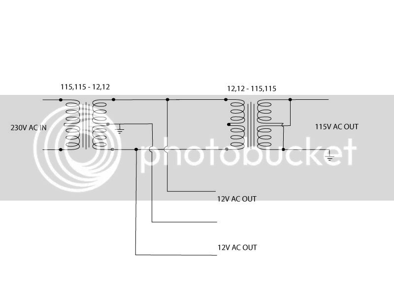
I think the problem might also be the power supply. I had to hook up 2 transformers back to back to get 120V cause I live in a country with 240V power.

The following diagrams shows how I connected the transformers:
PRR-Power-TX.jpg


Is this correct?

Or is the center tap causing problems?

Should I get a second transformer just for the HT?
J


I think the transformers aren't connected right.
Here's what I did and it worked :
 

Attachments

  • PRR-Power-TX modified.jpg
    PRR-Power-TX modified.jpg
    46.6 KB · Views: 34

Latest posts

Back
Top