You are using an out of date browser. It may not display this or other websites correctly.
You should upgrade or use an alternative browser.
You should upgrade or use an alternative browser.
Raytheon 5784WB as sub for AC701?
- Thread starter riggler
- Start date


Help Support GroupDIY Audio Forum:
This site may earn a commission from merchant affiliate
links, including eBay, Amazon, and others.
bockaudio
Well-known member
Nope. Think about it, an AC701 is a high Z tube. 5:1 will load it down.The original BV11 is a 5:1 ratio transformer.
MagnetoSound
Well-known member
C2 is shunt feedback - tiny, tiny value. Is that going to do any more than ensure stability / roll off RF?
riggler
Well-known member
C2 ---- Now I think it's DC blocking or a form of feedback control.
The node between the capsule and grid is there to get our reduced heater voltage to the grid, combined with the output of the capsule, to give us our bias and signal mix. But why does that node need to go up to the plate through C2? The only thing that makes sense to me right now is that it's an adjustable capacitor (abgleichen means to tune or match) used to somehow tune the circuit for the capsule? Or is it to adjust plate versus bias...
Thinking about it a little more, that C2 is another pathway for electrons to take rather then from the grid to the plate.
Could this be to prevent oscillation?
Looking all over the Neumann page. Found an article on "Omnis and Spheres", no detail on schemos. Back to locking later tonight.
riggler
Well-known member
Magneto, I guess I ended up thinking along the same lines as you! (We posted at the same time...)
> looks to me like the plate should get positive voltage through R8.
It does. How much current flows in R8? (Don't peek at "ca. 0,73mA".) That determines plate voltage. However the tube current is influenced by plate voltage. The solution needs simultaneous equations or successive approximation.
In a "simple" self-biased stage... well, take the Fender guitar-amp 12AX7. Mu=100, Rk=1.5K, Rp=100K. Quickly, figure Rk*Mu, tube acts like 150K resistor. For a better guess, look-up and add the Plate Resistance for a similar current. (1.5K*Mu)+60K, tube acts like 210K resistor. In series with a 100K resistor, the plate voltage will be like 210K/(100K+210K)= 0.677 times supply voltage. For B+=300V, we expect 203V at plate. We actually find 210V with at least 10% variation tube to tube.
The M50 is far more complex. Don't ask me what R2 is for (it may be for injecting test tones).
However, used with the specified '701, it is interesting that the 1.6V "forced" on the grid-cathode port is explicitly marked on the datasheet. And plotting 100K down from 112V (116V-4V) intersects that line at some point.
Spoiler: For another tube, find 0.73mA and 39V, a known-good operating condition for pushing signal through this transformer and typical mike lines. See what grid bias is needed. Compare that to your hyper-clean heater voltage, and compute a divider to make that much, reading down from cathode. The divider impedance should be much higher than heater impedance (little power/heat loss) but lower than grid-circuit resistance (mostly R1). In this case you have enormous latitude. R4 R5 OTOO 100 ohms or 1Meg will be OK, the ratio is the main point.
> Why do we need C2 at all though??
It is marked "0...2pF". Apparently there is some situation where we would install a zero pFd cap. At the other extreme, 2pFd added is awful similar to the 1.6pFd inside the tube.
IF the tube had infinite gain, then the 75pFd capsule against say 2pFd plate-grid forms an OpAmp, capacitive source, capacitive feedback. The gain from diaphragm to plate would be exactly 37.5. If tube gain is less than infinity, gain is less. If tube gain is less than 37.5, the simple 75:2 gain-factor is way off. We see on the sheet that similar conditions give gain of 9V/0.6V or 15. So the 0...2pFd has very little effect. I'm guessing it is used to hide tube tolerances, so that every production sample has the "same" output within a narrow window of tolerance. And that if you have just one mike, or two and don't mind working the mixer gain a dB or three different, then you do not need C1.
riggler
Well-known member
PRR said:How much current flows in R8?
OK I am not peeking, am not reading the fine print either and will figure this out.
Ohms law for Amperage:
I = V/R
So, if it were just the resistor and the supply 116 volts in the circuit...
I = 116/100,000 = .00116A or 12mA
Now, it's not that simple. And this is where my mind loses it.
Following the current from the 116V source through R8 we hit C4 going to ground.
OK, an RC circuit right? http://en.wikipedia.org/wiki/RC_circuit
Formula for Series RC circuit voltages:
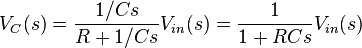
Formula for current:
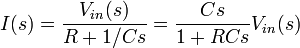
Assuming C means Farads and not uF...
I = (600,000,000,000,000/(1+(100,000*600,000,000,000,000)))*116 = .0016
A little perl confirms...
perl -e 'my $value; $value =((600000000000000/(1+(100000*600000000000000)))*116);print $value;'
.0016 or 1.6mA
Did I win the prize???? ;D
I was going to say that we have to consider the transformer here as another path to ground, but we don't, do we? (Because it does not couple DC, just AC to the secondary).
Now there's a boatload of other components here, and I am having a hard time knowing how to break this down --- knowing what affects R8 and what does not.
I would also say that tube "resistance" could make a voltage divider with R8, going through C3 to the transfomer. Aaaaaahhh, something just clicked as I typed that sentence... C3 strips off the DC leaving the tranny with our amplified signal.
So why are you telling me to adjust R5 to adjust plate voltage?? Why not R8? Assuming C2 is no longer there, we would get rid of it's nodes, too -- no wire link there either, right? If that's the case the only thing feeding the plate is R8. Although I guess all of the resistors have some effect on what voltage R8 sees, so... if we raise the value of R5, we lower the current and up the voltage. Does that effect continue to R6, R7, and R8 then even though there is a node at the +116 rail?
Oh, one more thing---- sorry --- but, the primary of the transformer acts like an inductor, doesn't it?
> I = 116/100,000 = .00116A or 12mA
Hasty arithmetic error.
What would be 100V and 100K? You should "know" this is 1mA.
Therefore your answer must be near 1mA, a hair more 'cuz 116V. You slipped a decimal point.
> Formula for Series RC circuit voltages:
Well, caps have NO effect at DC, which is what I was asking. So whatever this is, it isn't what we want.
To simplify, you have 116V battery, 100K resistor, and a tube. The tube could be anything, from a 4-foot transmitter monster to a nano-needle.... you gotta find out what it is. It can't be expressed as a single number like "100K", it takes a 3-dimensional plot to cover most questions. However the most useful thermionic triodes and most pressing questions can be rough answered with two of three parameters if measured "near" the actual operating point.
> 1.6mA Did I win the prize?
You got a looks-close answer the wrong way. What do you have for "s"? It should be jw. Frequency. For DC questions ("what is the steady idle current?"), it must be zero. Therefore the current must be zero. Which is correct (DC current in cap is zero), but we want resistor and tube DC current.
2 points for energy.
riggler
Well-known member
Insert Quote
> I = 116/100,000 = .00116A or 12mA
Hasty arithmetic error.
Duh, you're right. It visibly "looks it" from knowing the formula. Got it.
> Formula for Series RC circuit voltages:
Well, caps have NO effect at DC, which is what I was asking. So whatever this is, it isn't what we want.
Okay, now this makes sense too. The RC network is for AC signals, which is why I use it when making speaker crossovers. Duh - didn't think about it that way. You make sense. Got it.
To simplify, you have 116V battery, 100K resistor, and a tube. The tube could be anything, from a 4-foot transmitter monster to a nano-needle.... you gotta find out what it is. It can't be expressed as a single number like "100K", it takes a 3-dimensional plot to cover most questions. However the most useful thermionic triodes and most pressing questions can be rough answered with two of three parameters if measured "near" the actual operating point.
Starting to lose you here... For this example, we're using the 5784WB tube. Got the datasheet. Page 8 gives us curves of Grid 1 voltage versus Plate current:

Based on your numbers from the spoiler(had to read it!!!!), I guesstimated the following point imagining where a curve would have been for 39 volts based on the 60 and 90 volt curves. I come up with about .7volts:

Did I get that right?
Back to the current through R8 question, if I have the curves in front of me, what are you plotting to arrive at the tube's value to do the math to figure the current through R8? Can you walk me through your brain-function for that? I am thinking that you must pick a grid voltage or plate voltage, figure the current you're drawing, then that will give you a resistance.
I'm trying!!!!!! Please don't give up on me.
> we're using the 5784WB tube.
Well, but we were looking at a Known Good plan with '701 tube. Reverse-design something that already works, to be sure of your method.
We have:
'701 tube
116V B+ to ground
cathode 4V higher
therefore 116V-4V= 112V from B+ to cathode
From the +116V to the +4V, the DC path is simply a 100K and a tube
the grid is forced 1.6V negative of cathode, no matter what

They say 39, I say 41, close enough to rock.
As for that 5784... there is no simple curve for Triode mode, nor a pentode curve for G2 anywhere near the expected ~~40V.
The curve you printed can be re-complied for triode. Assume we will leave G3 at zero (it may not matter a whole lot). Take curves for plate and G2 at same voltage. Add the currents. this is the triode curve AT FIXED PLATE VOLTAGE and a range of G1 voltages.
So we can directly draw 150V, 120V, 90V, 60V. We want something near 40V. The curves are fairly regularly spaced, so we could extrapolate down to a 40V curve. This gets real messy. I put 2 cents on "1.8V", the pink smear shown here:

If we stuck with 1.6V fix bias (ah, but we are also changing the 4V to 6V so this will change), then it seems to imply say 1.1mA. But if 1.1mA flowed in 100K from 112V, the plate voltage is zero. We need to draw a plate curve for zero voltage, though clearly this will tend to be zero current. If you are trying to set fixed-bias to get a specific plate voltage/current condition, it is very fussy, and often best determined by experiment.
I'd be inclined to switch to self-bias. But that gives a loss of gain, or puts a large short-life Electrolytic inside the mike.
Well, but we were looking at a Known Good plan with '701 tube. Reverse-design something that already works, to be sure of your method.
We have:
'701 tube
116V B+ to ground
cathode 4V higher
therefore 116V-4V= 112V from B+ to cathode
From the +116V to the +4V, the DC path is simply a 100K and a tube
the grid is forced 1.6V negative of cathode, no matter what
They say 39, I say 41, close enough to rock.
As for that 5784... there is no simple curve for Triode mode, nor a pentode curve for G2 anywhere near the expected ~~40V.
The curve you printed can be re-complied for triode. Assume we will leave G3 at zero (it may not matter a whole lot). Take curves for plate and G2 at same voltage. Add the currents. this is the triode curve AT FIXED PLATE VOLTAGE and a range of G1 voltages.
So we can directly draw 150V, 120V, 90V, 60V. We want something near 40V. The curves are fairly regularly spaced, so we could extrapolate down to a 40V curve. This gets real messy. I put 2 cents on "1.8V", the pink smear shown here:
If we stuck with 1.6V fix bias (ah, but we are also changing the 4V to 6V so this will change), then it seems to imply say 1.1mA. But if 1.1mA flowed in 100K from 112V, the plate voltage is zero. We need to draw a plate curve for zero voltage, though clearly this will tend to be zero current. If you are trying to set fixed-bias to get a specific plate voltage/current condition, it is very fussy, and often best determined by experiment.
I'd be inclined to switch to self-bias. But that gives a loss of gain, or puts a large short-life Electrolytic inside the mike.
riggler
Well-known member
PRR!!!! HEY!!!
Well, I'm going to admit that my skull was exploding. I drew up a "triode" chart here per your instructions. Sorry, it's on paper, no scanner here.
Anyway, something dawned on me. I thought "Gee, I wonder if Raytheon made submini triodes. I looked here:
http://www.scottbecker.net/tube/sheets5.html
At a boatload of datasheets for these tubes and found this!!!!
http://www.scottbecker.net/tube/sheets/138/5/5703WB.pdf
The 5703 is:
A triode
Low-microphonic
Uses 6.3V heater
And the plate voltage chart looks darn close to the AC701...
(Page 5 of the datasheet)
So all we'd need to do to use this tube is tweak the heater voltage as discussed, and adjust cathode resistor for bias.
I am ready to have my parade "rained on"!
Cheers....
> "I wonder if Raytheon made submini triodes."
WHAT? Replace a triode with a triode? Stay on the Known-Good path?
Raytheon made a real business of it, but many others made teeny tubes, in about every possible form.
http://home.netcom.com/~wa2ise/radios/penciltubes.html
One thing to watch: these mostly divide into "normal" tubes in small bottles (~~1 Watt heaters), and "hearing aid" tubes (~~0.1 Watt filaments). The hearing-aid tubes are exceptionally low-power output. One company is new-making tube mikes with hearing-aid tubes; with super-clever design it gives adequate output using only Phantom power. But in general the "normal" tubes will be far easier to design with.
At a glance I see that 5703 at 40V and 0.7mA wants like -1.2V bias. It is not really as-good-as '701 for mike-use(*); but there may be a crate of Cold-War spares waiting for buyers.
Some of these may have been announced but never got any orders... part one of your adventure is finding the low/medium-Mu single triodes for which you can A) find full specs B) actually buy one and a spare.
(*) Few tubes are. 5703 sheet says design-max grid resistor is 1.2 Megs. The microphone circuit has 150 Megs, and for full bass and low bass noise you need something this large. '701 was designed for very-very-very low grid current. Other tubes have "low" grid current, but not tested past the point that would make trouble in a typical 1Meg resistor. Problem? Probably not. The 1 Meg spec is worst-case: bad day on the sealex machine, and a socket which pushes other parameters to the limit. If you aim for the edge of destruction, a large grid resistor and a poor-vacuum tube may put you past the edge. But the low supply voltage and large 100K resistor mean there is no great power dissipated or available. So most tubes will bias-up fine even with "over spec" grid resistor; those that don't will just bias wrong, won't smoke or melt.
After all, 12AU7 is specced 1Meg max, but several mikes use it with much larger grid resistors.
MagnetoSound
Well-known member
The 5703 is used in the Berliner U77, as well as some Korby stuff, I believe.
[quote author=MagnetoSound]
PS @ riggler - I've also had good results with 5840 and 5703.
[/quote]
[quote author=MagnetoSound]
PS @ riggler - I've also had good results with 5840 and 5703.
[/quote]
strangeandbouncy
Well-known member
Hi Guys,
http://cgi.ebay.co.uk/One-Fully-Tested-NOS-Vacuum-Tube-5703-5703WB_W0QQitemZ140249358729QQcmdZViewItemQQptZVintage_Electronics_R2?hash=item20a7836189&_trksid=p3286.m63.l1177&_trkparms=|293%3A1|294%3A50
you're in luck!
Kindest regards,
ANdyP
http://cgi.ebay.co.uk/One-Fully-Tested-NOS-Vacuum-Tube-5703-5703WB_W0QQitemZ140249358729QQcmdZViewItemQQptZVintage_Electronics_R2?hash=item20a7836189&_trksid=p3286.m63.l1177&_trkparms=|293%3A1|294%3A50
you're in luck!
Kindest regards,
ANdyP
MagnetoSound
Well-known member
I got mine here - half the price!
http://store.triodestore.com/ottub12a6thr.html
(Scroll down. They also have 5784 and 5840 right below it.)
http://store.triodestore.com/ottub12a6thr.html
(Scroll down. They also have 5784 and 5840 right below it.)
riggler
Well-known member
Magneto -- I am kicking myself for not looking into the 5703 when you posted!
PRR, So with this guy:
1.) Get heater voltage to 6.3V and supply enough current (datasheet pg 4 says heater will draw between 180 and 220mA) from PSU.
2.) Get bias to -1.2V (per the graph on page 5 of the datasheet, read you loud and clear) by changing value of the voltage divider R4 and R5? Or just R1?
And... the heater voltage coming in will be +6.3V. The bias voltage needs to be negative. Even on the M50 schematic the negative sign isn't there because it's assumed you know it has to be negative voltage. Fine.
But, how are they achieving a negative voltage from a positive voltage source?
Aaaaah wait... it's point of reference... one probe of the meter is at the node of f1 and cathode. That's at 4V (talking original M50). My other probe goes to the grid and that's at 2.4 volts. So the meter gives me a negative 1.6v reading. Am I on the right track or am I hosing the concept here??
So if I AM right, what I want to do for the 5703 is get the grid (referenced to ground) 6.3V - 1.2V = 5.1V
Then when the grid is referenced to that f1 node, I would get a -1.2V reading. I hope I make sense, or at least my thought process does...!
At a glance I see that 5703 at 40V and 0.7mA wants like -1.2V bias.]At a glance I see that 5703 at 40V and 0.7mA wants like -1.2V bias.
PRR, So with this guy:
1.) Get heater voltage to 6.3V and supply enough current (datasheet pg 4 says heater will draw between 180 and 220mA) from PSU.
2.) Get bias to -1.2V (per the graph on page 5 of the datasheet, read you loud and clear) by changing value of the voltage divider R4 and R5? Or just R1?
And... the heater voltage coming in will be +6.3V. The bias voltage needs to be negative. Even on the M50 schematic the negative sign isn't there because it's assumed you know it has to be negative voltage. Fine.
But, how are they achieving a negative voltage from a positive voltage source?
Aaaaah wait... it's point of reference... one probe of the meter is at the node of f1 and cathode. That's at 4V (talking original M50). My other probe goes to the grid and that's at 2.4 volts. So the meter gives me a negative 1.6v reading. Am I on the right track or am I hosing the concept here??
So if I AM right, what I want to do for the 5703 is get the grid (referenced to ground) 6.3V - 1.2V = 5.1V
Then when the grid is referenced to that f1 node, I would get a -1.2V reading. I hope I make sense, or at least my thought process does...!
MagnetoSound
Well-known member
You're on the right track, the grid just wants to be 1.6v negative w.r.t. cathode.
(BTW, not to distract from what you are doing, but there is no law that says you must have a positive filament supply. As an eye-opener, take a squint at the U67 circuit. The novelty there is that the cathode is grounded, and the heater supply is negative. The grid bias is still divided off the heater supply, it's just another way round of doing it.)
(BTW, not to distract from what you are doing, but there is no law that says you must have a positive filament supply. As an eye-opener, take a squint at the U67 circuit. The novelty there is that the cathode is grounded, and the heater supply is negative. The grid bias is still divided off the heater supply, it's just another way round of doing it.)
tubologic
Well-known member
- Joined
- Mar 29, 2009
- Messages
- 72
riggler said:Poking around Klaus's forum, I found this:
http://recforums.prosoundweb.com/index.php/t/2927/0/
(Go about halfway down).
And I quote:
In case anyone needs a substitute submini for use as a capsule amplifier, you might want to try out a Raytheon 5784WB wired G2+G3+P=triode. This is one of the very few submini pentodes that can be wired this way - most have G3+K as an internal connection.
Note I have not used an AC701 and can't compare if it would be a similar sound. I can only say that after testing many different submini triodes and pentodes (wired as triode), I found the 5784WB to be quite good in all aspects. IMO similar to FET sound, only the things I don't like about FET sound are fixed - i.e. it's unconstrained and open sounding while being otherwise similar.
End quote.
Can anyone here corroborate this? I'm going to try it with my M50 project if no one sees an obvious issue. A look at the datasheets...
5784WB
The 5784WB is a dual control pentode that can be used as an AF / RF amplifier or mixer.
Filament 6.3V/.2A. Plate 120 Volts / 5 mA. Gm 3200 uMhos.
AC701(k)
http://tubes.mkdw.net/sheets/128/a/AC701.pdf
Filament 4V/.1A. Plate (120V? Could use some help here interpreting the data from the sheet...)
Thanks for any info / ideas.
Sorry to say, but the 5784WB (and most other subminiature tubes intended for military/computer/hearing aid purposes) are not suitable as a substitution for the AC701K.
The fact is that there are no good (and cheap) substitutes for the AC701K for many reasons. Remember the AC701K was speciallly designed for condenser microphone preamplifiers and has very low noise,high insulation resistance (low leakage) and very low grid current. None of these criteria's are met by the common subminiature tubes. Actually,the AC701K looks more like an electrometer tube and I strongly suspect its design was based on such a tube. (Like the electrometer tubes,the AC701K is highly photosensitive and painted in black for this reason). If you look at the spec's,the grid current for the AC701K is given for 100 pA (Picoamperes !) and typically between 100 and 300 pA, which is extremely low. In comparison,the 5784WB has a grid curent of 300,000 pA (Yes,at least one thousand time more !) with a specified 1 megohm input grid resistor. Remember we're dealing with very high input grid impedances (in the order of hundreds of megohms) and very low grid input current (and low leakage) are an absolute must for this application. Most ordinary receiving (and subminiature) tubes can't be used with grid return resistors higher than 10 megohms (Design maximum for the 5784WB is 1.2 megohms). What does all this mean ? If you substitute a 5784WB (or other similar tubes) for a AC701K you will end up with highly unstable (and unpredictable) plate current (which means lots of NOISE) and highly degraded performances, whatever circuit changes you may try.It will probably "work" but It will be a poor mic as far as performances and sound are concerned. The AC701K is a very peculiar tube and there are reasons why it is (and allways was) expensive,and nearly impossible to substitute. For new designs there are probably some alternatives: you'll need a tube (triode) with similar electrical characteristics and extremely low leakage and grid current. All-glass construction with very short output leads will contribute to this. No know subminiature tube has a separate grid connection on the top of the bulb (like the AC701K) except the EC1000 (a PHILIPS special quality subminiature triode for measuring probes),probably the closest to the AC701K you may find but unfortunately with a too high grid current. (10,000 pA),certainly worth a try... if you can locate one ! Most electrometer tubes (CK5884/5885/5886 , ME1401/1402,etc...) will satisfy the low grid current criterion but are designed to work at very low plate voltages (around 10 - 20 volts) and plate currents (microamps) which make them unsuitable for our application. The best candidates would be small VHF/UHF triodes which have inherently low inter-electrode capacitances and low leakage.(but could be very microphonic) I tried many tubes and so far had the best results with the 1650 acorn tube, which is the low-leakage version of the venerable 955 triode. There are probably other tubes but experimentation (AND READING THE CHARACTERISTICS !) will be needed. This will make the difference between a average microphone and an exceptional one,like the old NEUMANN's.
To summarize: The AC701K was an outstanding but peculiar tube,don't expect to replace it with a cheap hearing aid or shell proximity fuse subminiature tube. Both are small and made of glass (and metal),but that's all they have in common.
MagnetoSound
Well-known member
>The fact is that there are no good (and cheap) substitutes for the AC701K for many reasons.
Nobody said it was a like-for-like replacement.
While I am sure that all those of us who service microphones for a living would agree that the idea of using any other tube as a replacement for AC701k in a vintage mic is unacceptable, the OP asked a reasonable question IMO, as to whether a substitute tube could be made to work in a DIY project, where a 701 would be impractical due to cost.
If you really feel that these JAN sub-minis are as crappy as all that, perhaps you should tell all the manufacturers (Neumann included) that are making good use of them in their current products.
Just sayin' ...
Similar threads
- Replies
- 25
- Views
- 10K