SSL 9K & 4K (E Series) 500 / 51X NEW BOARDS Mic Pre Thread 2011

GroupDIY Audio Forum

Help Support GroupDIY Audio Forum:

This site may earn a commission from merchant affiliate links, including eBay, Amazon, and others.
Sorry about the transformer error!  I just used the published footprint, but didn't have the transformer in hand to try.  Looks like the whole transformer footprint is flipped, damn.
Guess you'll have to do the mod like you planned, or use the adapter.  Really sorry about this!
Best,
Bruno2000.
 
One down three to go.  With one small problem the unit works very well except none of the LED's work.  It passes audio (Sounds Great) and all of the switches and pots work,  just no LED's.  When I turn the 48 volt switch on the power supply for the API 500 rack I get a slight Led glow from the 48 volt LED on the SSL9K if I turn it on.  This one has me stumped I disconnected the meter bar to check just the switch LED's still no power there. I know there are different voltages for the 51X but I did not see any alternative parts in the BOM thinking maybe I used something I was not suppose to.  I triple checked for shorts found none. I included pictures maybe some one can see if I did something wrong or have an idea were to start looking.

100_1048.jpg
100_1044.jpg
100_1038.jpg


Thanks
Kim 
 
culteousness1 said:
kquick said:
... just no LED's...

Some basic questions:

Did you check the LED direction?
Did you check the voltages at the meter board?
Did you do the meter/ground work around?

Let's get it sorted!

Best,
Carsten

Carsten,
    Thank you for the help.  It was the LED direction.  First build I have done with LED's, I seen the longer leg on one side like a capacitor but could find no markings like a + symbol on the pcb, searched the internet but could not find any info so I put them all in the same way.  Could you explain to me what to look for to tell the proper direction so that I do not make the same mistake again.  It was a night mare changing them on the little meter board.  But the good news is every thing is working fine.

Thanks Again
Kim
 
You can see on schematic that leds have common anode (positive pin)... On pcb is easy to se what pads are common and which ones come from IC  :)  On mechanic side I normally can see that the cathode is the bigest part inside the plastic lens... the coup part... sometimes i have recycled leds  :p
Basically if silkscreen does not tell you polarity you can always look at the schematic and compare with the pcb...

Hope it helps

Arnau
 
Apache5 said:
You can see on schematic that leds have common anode (positive pin)... On pcb is easy to se what pads are common and which ones come from IC  :)  On mechanic side I normally can see that the cathode is the bigest part inside the plastic lens... the coup part... sometimes i have recycled leds  :p
Basically if silkscreen does not tell you polarity you can always look at the schematic and compare with the pcb...

Hope it helps

Arnau

Arnau
    I understand it now thanks for the answer. :)

Kim
 
Very nice build, congrats!  The first post has photos of how to bend the LED leads, and as you can see, one lead is longer, and they all go in the same way.  Good explanation from Apache5.
Hope you enjoy them.
Best,
Bruno2000
 
bruno2000 said:
Very nice build, congrats!  The first post has photos of how to bend the LED leads, and as you can see, one lead is longer, and they all go in the same way.  Good explanation from Apache5.
Hope you enjoy them.
Best,
Bruno2000

Thanks Bruno I have to say I really like the sound of this pre was very impressed, Now I cant wait to get the other three done.

Kim
 
Bruno....

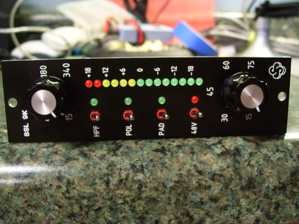
Had a couple of phase problems, and traced it back to the Polarity switch on the 9k5 preamp.  It turns out, on mine anyway, the default phase is 3 hot, 2 cold, 1 gnd.  Which is switched from normal.

I was wondering if I am using the wrong type of relay perhaps (OMRON G6A-234P-ST-US-12VDC), but I just found the aromat http://pewa.panasonic.com/assets/pcsd/catalog/ds-catalog.pdf and it appears to be the same.

The Aromat DS catalog says that it is possible to special order reverse polarity Relays but lead times are long unless someone knows where to go.

I could just fix it by leaving the polarity light on but there must be a better way. 

Did I use the wrong relay?  Is there a right one? Know where to get it?

The default position for this relay is shown in the photo.( iPhone photo through a jewlers loupe!)

Anyway,  I was thinking that the default position of the relay is incorrect or unexpected, or is it just a bug in the board, in which case, what do I do?  I am thinking a little creative crossing of the leads on C4 and C5?

Did some more looking.  I really don't get it.  If the part is wrong, then the other three switches should also operate incorrectly.  phantom should be off when I turn it on, etc.

So what gives?
 

Attachments

  • omron photo.jpg
    omron photo.jpg
    288 KB · Views: 77
Has anyone else checked the phase (Polarity) out on the SSL 9K 500 Series board?  Mine is backwards, and I cannot figure out why (bad relay choice specified?). Any board mod suggestions to fix this?
 
hi bruce0..
just realized I have the same problem - no Idea why - I'm not using mine in a Rack so I just swapped pin 2 and 3 on output XLR.
 
I got confirmation that the polarity is reversed, and a suggestion that I think works, which is that each of the board edge fingers has a pad next to it, so it is pretty easy to cut 2 traces, and put jumpers in to cross the polarity.

As i mentioned, there is also a reversed polarity version of the relay available.  If I can find that, it think that would be easiest but the other is no problem.

 
cool idea with the jumpers..... but if we used the wrong part , I used mouser part: 653-G6A-234P-DC12 , why is the HPF , the pad or the phantom switch correct?
 
morbleu said:
cool idea with the jumpers..... but if we used the wrong part , I used mouser part: 653-G6A-234P-DC12 , why is the HPF , the pad or the phantom switch correct?

You used the right part. The output traces from the polarity relay are wrong.  This will be fixed in the next run. The jumpers are the easy fix for now.
Best,
Bruno2000
 
Could some one post a diagram of which two traces to cut and jump? I know its the RL3 relay but not sure were to go from there.

Thanks
Kim
 
Hi all,

I am just about to finish three 4Ks. So far no problems after first fire up.
Just need a proper loading and zobel for the oep trannies.

Am I assuming right that R8 is the loading resistor, R16 is R_zobel, C11 and C18 are C_zobel?

I found a value for C_zobel = 800 pF in another thread. This means I need 330 pF || 470 pF.
Without having the board at hand, are C11 and C18 in parallel? A schematic might be helpful. Found myself  :-[

Cheers,
Carsten

This is the thread I am referring to:
http://www.groupdiy.com/index.php?topic=6045.0

EDIT: Went through the thread again...
 
kquick said:
Could some one post a diagram of which two traces to cut and jump? I know its the RL3 relay but not sure were to go from there.

Thanks
Kim

Here ya go!
 

Attachments

  • SSL 9K 51X 42xSIGPolFix.pdf
    215.7 KB · Views: 157
Calibration done  8):

4K_1.jpg

4K_2.jpg


Ended up with just a load resistor of 27 kOhms. Maybe I will add a Zobel later on.

Thanks again to Bruno2000, Frank at NRGcnc and Gustav!
Hope to take it to the studio soon for a comparision with the 9K.

Cheers,
Carsten

 
Back
Top