SSL 9K & 4K (E Series) 500 / 51X NEW BOARDS Mic Pre Thread 2011

GroupDIY Audio Forum

Help Support GroupDIY Audio Forum:

This site may earn a commission from merchant affiliate links, including eBay, Amazon, and others.
Hi again,

a warm thank you to Bruno2000, Gustav and Colin for this great project. A great PCB layout, easy to stuff, an overall very well documented project, thanks a lot !!!

Here are a couple of pictures as a follow up to my BOM that you can find in the preceeding post.

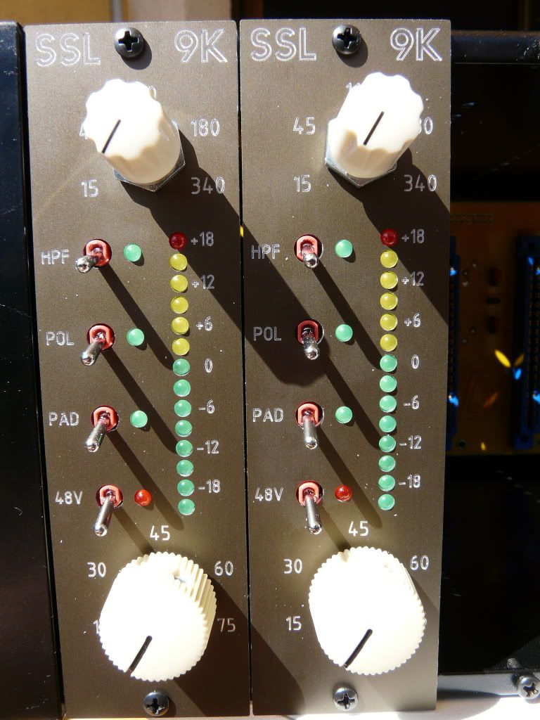
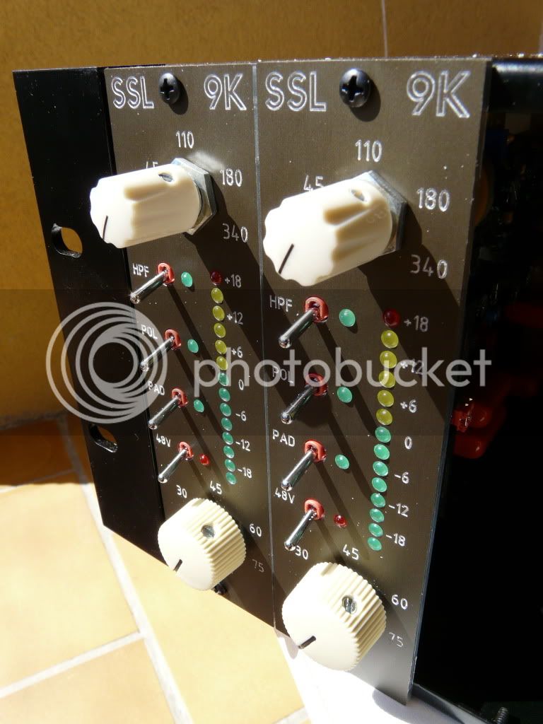
For the front panels, I've customized Bruno2000's fpd file in the Front Panel software for Mac and sent it off to Schaeffer AG in Germany. The bronze panels showed up in a couple of days, a great first experience with Shaeffer. There's no ink filling and two panels cost me 53 euros.

Knobs I've bought at Das Musikding.

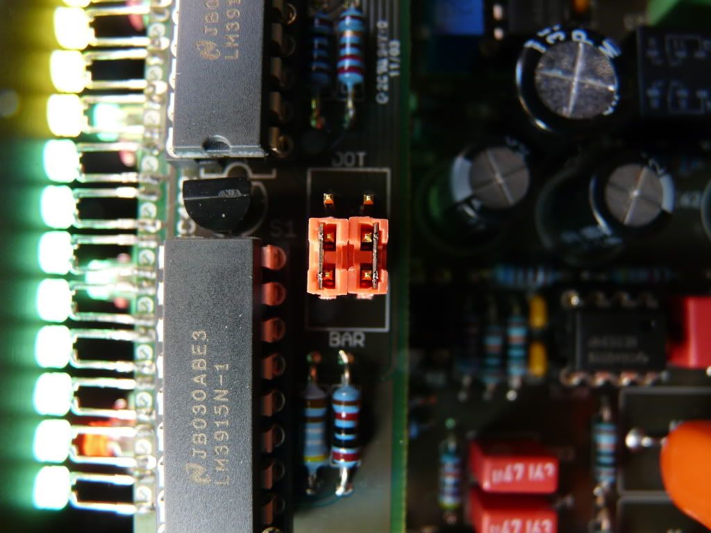
I had some headers and shunts left from the 51X rack build which I've added so you can always choose the mode in which the leds light, either DOT or BAR. I've read somewhere (where ???) that in BAR mode the current draw was a little over the 130mA per module limit, so this may reduce it...in case it's ever needed.

For calibration, I've followed the pretty straight forward instructions by Bruno earlier in the thread, went like a charm.

P1080183.jpg

P1080181.jpg

P1080185.jpg


Have a nice day !!!!!!!!!!!!!!!!!
 
loving my Bruno/9k's
Wanting another.... but does anybody know where one can get the pots for this?
 
bruce0 said:
loving my Bruno/9k's
Wanting another.... but does anybody know where one can get the pots for this?

Glad you like them!  Colin (Audio Maintenance) should have the pots in stock soon.  See a few pages back.
Best,
Bruno2000
 
Well, I finally managed to finish my 2 9K boards thsi morning, pluged them in... and neither did work.

There is some sound passing thru, but highly distorted and very very low, even with max gain. There are cracks and pops too, and every switch makes a loud "bang" when switched, especially the pad. 48V is fonctionnal, I tried with a condenser mic, but same sound.

I'm bummed because whatever mistake I made, I made it twice on my 2 boards !
 
NoBass said:
Well, I finally managed to finish my 2 9K boards thsi morning, pluged them in... and neither did work.

There is some sound passing thru, but highly distorted and very very low, even with max gain. There are cracks and pops too, and every switch makes a loud "bang" when switched, especially the pad. 48V is fonctionnal, I tried with a condenser mic, but same sound.

I'm bummed because whatever mistake I made, I made it twice on my 2 boards !

If you plug them in together, and one of them is shorting (or heavily loading) a rail, you might get that effect.  Maybe you could try to test them one at a time, and also perhaps put a voltmeter on each 16 v rail to ground.  The relays except phantom run off the negative rail I think (do those led's light?) so that may give you a hint.  Phantom I think is just a switch, no relay - led lights off the 48v.

I had similar symptoms when I had the current limit set too low on one rail on my bench supply (noise, crackle but the relays worked (I don't know if they popped).

Unless you are sure of the rack power situation, check the rails with no cards installed first.

And  I must add.... kudos and thanks to Bruno for providing a schematic... if only all DIY boards had schematics!

There is a schematic earlier in the thread, but added here for your convenience
 

Attachments

  • SSL 9K-42Sch.pdf
    92.2 KB · Views: 85
Well, I just thoroughly checked my rack power supply, and everything seems okay, with or without modules installed.

So the problems lies within my SSL 9Ks.... Everything lights up (I didn't install the metering), every relay seems to work.

The thing is, I have an extremely limited understanding of electronics, so the schematics isn't really helping me... I don't know where the problem is !
 
NoBass said:
Well, I just thoroughly checked my rack power supply, and everything seems okay, with or without modules installed.

So the problems lies within my SSL 9Ks.... Everything lights up (I didn't install the metering), every relay seems to work.

The thing is, I have an extremely limited understanding of electronics, so the schematics isn't really helping me... I don't know where the problem is !

Can you post a good photo of one of the cards (since they both have the same problem),  A couple of closeups maybe?
 
I think I see the problem.

There is a rectifier on the board, and the rectifier has 4 terminals two are marked with a wave, and two are marked with + and -.  The circuit board has similar marks on it ( S  S  +  - ) but the markings are very small.

There is a type of rectifier that comes in a little square chip package, and fits right in there, but you used one of those W0G packages (i think that is what they are called.).  I used one too, and it worked, but I crossed the legs to make the correct leads go to the correct place, and it worked fine.

The waves have to go to the Waves (doesn't matter which goes to which), and the + must go to + and the - must go to -.

(the marks on the PCB are small, use a magnifier...).

In your photo, it looks like you have the negative lead going to one of the wave sockets.

You can see this rectifier at the output of the THAT chip on the schematic.  I don't know what effect you may have had on that THAT chip other components, but start with fixing the rectifier installation.

If you want a mouser part number that will drop right in, I think these will work (I am planning to use one of them for my next Bruno 9k, I am ).  The pins are arranged like the circuit board contemplated when designed.

http://www.mouser.com/search/refine.aspx?Keyword=821-DB153G
http://www.mouser.com/search/refine.aspx?Keyword=583-DB101C


You may be lucky.... I looked at the schematic, The way you had it configured (but it is hard to tell the picture is fuzzy ) it looks like it was grounding one side of the output of the That Chip whenever the output signal was above ground potential.  When you switched the polarity relay it would ground the other side (that could be pretty loud!).  I don't know if grounding one output of a THAT chip hurts it probably not.  Could have been worse, the + terminal is 15V, and might have effected other components (and even whatever you connected it to). 

Anyway I hope this helps.
 
Hi NoBass,

I second BruceO, you regulator does seem wrong, the pinout of the one you are using does not fit the PCB nor the circuit for that matter. Here's the Fairchild I used (pdf) and a little explanation to feed your thirst of electronic knowledge  !!!  (http://hyperphysics.phy-astr.gsu.edu/hbase/electronic/rectbr.html)

On a side note, the two SSL9K-51X I've built lately (top of this page 8)) have served me great on a session I'm recording these days with a female punk rock band. I've used them on kick, snare, vocals and they've been rock solid and precise. A pleasure to use !

So repair yours and enjoy !!!!
 

Attachments

  • Bridge Rectifier - DF06M.pdf
    113.4 KB · Views: 33
Regarding this take on the 9k what was the reason why C9 was required, keeping in mind that it comes right after the servoed IC24?

ssl_9k_crop.gif
 
mnats said:
Regarding this take on the 9k what was the reason why C9 was required, keeping in mind that it comes right after the servoed IC24?

ssl_9k_crop.gif

My thinking was that if IC24 failed, it would keep DC from the next stages.  You could probably short it out if you wanted.
Best,
Bruno2000
 
bruno2000 said:
My thinking was that if IC24 failed, it would keep DC from the next stages.  You could probably short it out if you wanted.

OK, I was just hoping that I wouldn't have to place another Mouser order with a $30 freight charge for a few bits and pieces.

Thanks for the design, by the way - I've had a pair of 9k pres on the back burner for so long that I almost forgot about the box of parts I had for them. The pair of MAT02EH from Digikey is marked 23 APR 2007!
 

Latest posts

Back
Top