bruno2000 said:
I bought a bunch of MAT02s form a Chinese source for use in some SSL 9k preamps. I did a spot check with my cheap DVM, and the hfe reading on them was anywhere from 640 to 730 (Ib=10uA Vce=3V), but the 2 “sides” were usually matched well, within less that 10 units. Is there a better way to “select” these transistors for use in the 9k?
Transistor matching mini-HOWTO
(also usable as a rough way of telling if your MAT-02 is real or fake)
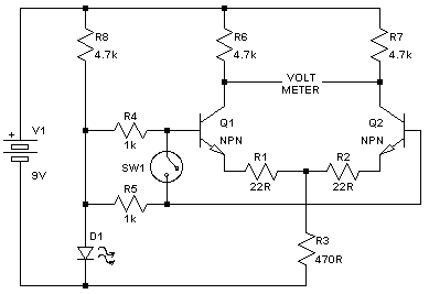
Build this circuit:
D1 is a red LED, or really any LED with a forward voltage of 1.5..2V when biased with a 4.7k resistor from a 9V supply. The 9V supply can be a battery, which'll last for 50-60 hours of continuous operation. A stabilized supply somewhere between 9 and 15V will do fine too. Put a multimeter set to its smallest voltage range between the collectors of the transistors (ie: where it says VOLTMETER). Keep the wires in the base circuit short, don't mount the switch further than a few centimeters from the transistors.
It helps to match the resistors, ie match R1 and R2, R4 and R5, R6 and R7. Just go through your parts drawer, measure the resistances and pick resistors that are close in value. If you're feeling particularly anal you can always install trimmers.
Principle of operation: this is a bog-standard differential long-tailed pair. D1 and R3 set the total current to approx 2mA or 1mA per transistor. Amplification is RC/(RE+re) or about 100x for the selected values.
Procedure:
0) If you're testing MAT-02s, first measure hFE like bruno2000 explains above. Check with the MAT-02 datasheet if these are above the minimum (>400, IIRC).
1) Connect transistors to the circuit, close SW1. The value on the meter is a representation of the difference in VBE. Again, if testing MAT-02s see if this value divided by the ~100x amplification falls within tolerance. I believe the worst grade of MAT-02 has a voltage offset over full VCE of +/-200uV, so readings between -20mV and 20mV are acceptable.
2) Open SW1. The reading now shows the difference in VBE (as measured in the previous step)
plus a measure for the difference in hFE. The math here is a bit more involved, but if this reading is within 10mV of the previous one the device is within spec here too.
Now what if you don't want to test a MAT-02, but you have a bag full of TO-92 transistors and you want to find a closely matched pair? Then:
(optional step 0: measure hFE for all parts, and select (say) the 25% top-hFE transistors).
Step 1: Pick a transistor, any transistor, out of your pile. This will be your reference part. Label it, and insert it in the position for Q1. It stays there for the rest of the tests.
Step 2: For all other transistors, insert them one by one as Q2 and record the measured offset with the switch closed and opened.
Step 3: Parts for which the two measured offsets (switch open, switch closed) when compared to the reference transistor are closest, will also be close to each other. These are your matched pairs (or quads, if you're lucky).
Keep in mind that these transistor parameters are
very temperature sensitive, to the tune of ~200mV output change per degree Celsius. I have found that after inserting a TO-92 with my bare fingers it takes upwards of a minute for its temperature to cool back down to ambient. Use gloves, take your time, and keep the measurement setup out of the wind. Measuring the difference between two parts cancels some of the temperature dependence, but still it's not a good idea to test a batch when the room temperature is changing a lot. Also, consider a ZIF socket if you want to sort through lots of transistors.
You can see how well the setup is matched (the aforementioned resistors, really), in the same way that you would with a spirit level. If you swap Q1 and Q2, in a balanced setup the sign of the measured values will change but the magnitude will remain the same.
Now, there are some major simplifications in this setup; if you need more
accuracy you may want to go for something more like
Samuel Groner's. However, for a balanced input pair the
precision of the match is usually more important, and a simple plan as is sketched here will do just fine.
(An alternative way of matching transistors is to build a full SSL9k except for the input pair. Use sockets for the input pair, terminate the mic input with a 150R resistor, set gain to max by shorting out the gain pots. Measure the voltage between the outputs of the first stage (pin 6 of IC22 and IC29,
before the 2u2 capacitor); a transistor pair which gets this voltage closest to zero will be closely matched).
JDB.