You are using an out of date browser. It may not display this or other websites correctly.
You should upgrade or use an alternative browser.
You should upgrade or use an alternative browser.
U87 HF rolloff...
- Thread starter SSLtech
- Start date


Help Support GroupDIY Audio Forum:
This site may earn a commission from merchant affiliate
links, including eBay, Amazon, and others.
Where are all those cool schematics locted, Kubi's site or ijr, I spaced that link.
:shock:
:shock:
SSLtech
Well-known member
CJ,
Right-click the schematic, look at the properties and back-navigate to the omnipressor mic pre schematic library.
Keef
Right-click the schematic, look at the properties and back-navigate to the omnipressor mic pre schematic library.
Keef
David Satz
Member
- Joined
- Sep 25, 2004
- Messages
- 9
The degree of "de-emphasis" in the U 87 amplifier is being overestimated here, and the brightness of the capsule is being overstated. Take a look at the response curves for the USM 69 stereo microphone and you can see what the K 67 capsule does when no high-frequency rolloff is applied in the amplifier. The high-frequency elevation is significant but it's certainly not in the 10 dB range.
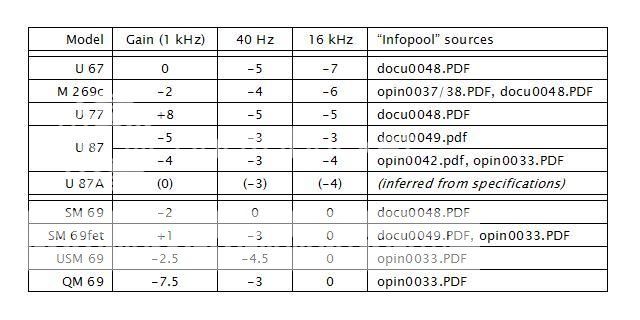
Neumann specifies the rolloff of amplifiers at 40 Hz and 16 kHz in their service publications; for the U 87 the high-end rolloff is specified as 3 dB (or in one edition, 4 dB) at 16 kHz, relative to the 1 kHz response. Paul Stamler is right that the rolloff was noticeably greater in the U 67: 7 dB at 16 kHz relative to 1 kHz. Incidentally, this means that you can't make valid judgments about "tube" vs. "transistor" sound by comparing U 67s with U 87s, as some people imagine they are doing.
The stereo and quad microphones based on this capsule design (SM 69, SM 69fet, USM 69 and QM 69) omit this high-end rolloff since it is assumed that the microphone will be used at some distance from the sound sources in a normally reverberant environment. The logic of that approach is open to criticism IMO, since concertgoers hear (and are presumably used to) the high-frequency losses that occur under those conditions.
--In the early 1990s, one of Neumann's customers ordered a batch of a few dozen microphones combining the electronics and pattern selection arrangement of the TLM 170 and the capsule arrangement of the U 67 or U 87 A. This model was called "TLM 171" and relatively few people have ever seen it, though one came up for auction on eBay two or three years ago. Anyway, Neumann lent a few of these microphones around to selected producers and engineers for their comment. The eventual result of that marketing research project was the Neumann TLM 103, which has about a 4 dB rise in the top two octaves.
--best regards
SSLtech
Well-known member
David,
Thanks for your wisdom. -excellent historical information as well as factual input!
Keith
Thanks for your wisdom. -excellent historical information as well as factual input!
Keith
EQ's applied to the K67-type capsule by different microphone architectures:
I don't remember where I got it... :?
Jakob E.
I don't remember where I got it... :?
Jakob E.
David Satz
Member
- Joined
- Sep 25, 2004
- Messages
- 9
> I don't remember where I got it...
Well, I rather expect that I know, since I made up that chart and posted it on Klaus Heyne's forum in late November, 2005, and that's the only place I've ever posted it. It was based on PDFs from the download section of Neumann's Web site that give the amplifier specs for most Neumann microphones up to a certain year of production--gain, noise, maximum input level at the front end, and 40 Hz and 16 kHz response.
All those files are still available, but some have been renamed--the ones which used to be opin*.PDF are now called copi*.PDF, with the same numbering. And finding specific files by name on Neumann's site has also become a bit trickier. Plus I've since noticed some of the same information is present in other Neumann documents which I didn't list. So to that extent the little chart is out of date, and I would ask people not to post it again. Still, I hope that the information concerning the microphones themselves is of some use. (The figures shown are in dB, obviously.)
--best regards
SSLtech
Well-known member
Hey David, I'm confused a little about the U87 numbers... one line indicates that one has a -5dB gain at 1kHz and a 3dB gain at 16kHz... an effective HF lift of 2dB... and another one 4dB at 1kHz and -4dB at 16kHz; inferring even gain in between, perhaps?
Anyhow, the REASON behind my asking is that I can't use the Neumann circuit to get TWO smultaneous back-to-back independant cardioid outputs from a pair of 87 capsules which I have here, so I wanted to add de-emphasis at line level, immediately after the preamplifier stage.
Anyhow, I'd really like to evolve a line-level 'correction' circuit, which means knowing the corner frequency, the degree of cut and perhaps another couple of details I suppose...
I'm really trying to get 4 flat quadrant outputs from a pair of U87 back-to-back capsule pairs in a blumlein type arrangement... and the capsule HF gain is a nuisance. -I suppose that if I had an anechoic chamber, I could measure it and do things that way, but I don't... :sad:
Keith
David Satz
Member
- Joined
- Sep 25, 2004
- Messages
- 9
Keith, no--the figures given for 40 Hz and 16 kHz response are relative to each model's own gain at 1 kHz, not to unity gain. Thus if your only concern is the high-end rolloff in the various amplifier circuits, you can ignore the 1 kHz figures completely, and compare the 16 kHz figures directly to each other. You can see a general progression in the single-channel microphones from the U 67 through U 87, in which the rolloff was gradually relaxed as newer models were introduced--Neumann made each successive generation just a tiny bit more detailed sounding than the generation before it. Whether this was driven by the market or was an attempt to drive the market (or both), I'm not sure.
Unfortunately the curves below 16 kHz aren't defined in the specifications. But there are test inputs on the circuit board of U 67s and U 87s that allow a signal generator to be attached directly. I'm surprised that no one (to my knowledge, at least) has published the complete curve of the amplifiers' frequency response. I can't measure this myself, since the only U 87 I still own has a modified amplifier, and I don't have the proper test head for shielding the amplifier's normal inputs while it's being measured. (Now I wish that I'd bothered the nice people at Gotham Service Lab about this while they were still in business.)
Some general indications can be gotten by comparing the published U 87 curves with the SM 69 and QM 69 curves. The multi-channel K 67-based microphones never had this rolloff at all, on the theory that with more distant placement on average, they would need some form of compensation for high-frequency adiabatic and reflective losses.
From my own experience with the SM 69fet and USM 69, however, I think that this may have been a mistake. Engineers don't generally make stereo recordings from all the way into the diffuse sound field in a reverberant space; we usually find a point that's somewhere near the critical distance, where the direct and reverberant sound energy balance one another. In that type of placement, the high-frequency response of the Neumann stereo mikes is often a bit excessive by modern classical standards, I'd say. And as I said before, concertgoers are completely accustomed to hearing those same high-frequency losses as a function of distance from the sound source; it sounds weird when you hear the brilliance of a close-up recording but the reverberance of a distant pickup at the same time. So I agree with your idea of compensating for this in a quad/surround/"sound field"-type microphone.
--best regards
Thanks, Mr. Satz!
:thumb:
Jakob E.
:thumb:
Jakob E.
SSLtech
Well-known member
Aha- (slaps forehead!!!) Ahy didn't I think of this!!!
I have a U87i here which I've just cleaned the capsules (after they grew an almost complete 'Afro' from being slid in and out of a slowly disintegrating foam-lined flight case drawer... I took photos of the capsule cleaning process in case anyone asked...) -so I presume that I could measure that...
I just need to get the test points and hook up the Neutrik... excellent thinking!
-Should I disconnect the capsule, short past it or replace it with a capacitance, or just sit very quietly in the room to prevent room noise from influencing the readings?
-Also, for clarification, the 1kHz figures are typical absolute gain/SPL numbers, and the HF and LF figures are presumably actual dB rolloff figures relative to each unit's mid-band reference gain, as opposed to being referenced to the same number as all the 1kHz figures... -Hopefully I've got that straight: it certainly makes more sense now!
Keith
David Satz
Member
- Joined
- Sep 25, 2004
- Messages
- 9
Keith, the test points are the parallel red and black rectangular thingies on the circuit board. As far as I'm aware, you can leave the capsule head attached if you're in a quiet enough place, but you may well get lots of hum--to make noise measurements, there's a special test set that includes replacements for both the capsule head and the amplifier sleeve, but without that test set, as I understand it, you're pretty much forced to leave the capsule head attached. The maximum input voltage should not exceed 320 mV according to the instructions on Neumann's site (copi0033.pdf). And yes, your explanation of the 1 kHz/40 Hz/16 kHz figures is right.
I really wish that I could post images or other files here, but I have no Web site so this doesn't seem to be possible. I've pulled together all the different Neumann frequency response curves I could find for microphones that use this capsule type, from the U 67 through the QM 69, and some of the comparisons would be instructive. I guess I'll just have to gesticulate wildly, and hope that you can get the picture via air motion from Brooklyn.
--best regards
dale116dot7
Well-known member
Oh boy - this is tricky one because the capsule 'floats'. In theory, you should have a signal generator in series with a 50 pF capacitor, and a 'dummy' 50 pF capacitor across the other (back) half of the capsule. The difficulty here is you have the feedback signal applied to one side of the capsule, and the output of the capsule taken off the other side. And all of the circuits assume a 50pF capsule capacitance and not a signal generator.
Now, this MIGHT work.... take 50 pF capacitors in place of the capsule (two capacitors). Now, couple, the signal to the gate (capsule output) using something like a 5 pF capacitor. That should maintain the feedback arrangement, and the signal output of the generator should be attenuated pretty close to correctly by the amount of feedback applied, plus by a factor of 1/11... I think.... You end up with a capacitive voltage divider doing that.
Now, this MIGHT work.... take 50 pF capacitors in place of the capsule (two capacitors). Now, couple, the signal to the gate (capsule output) using something like a 5 pF capacitor. That should maintain the feedback arrangement, and the signal output of the generator should be attenuated pretty close to correctly by the amount of feedback applied, plus by a factor of 1/11... I think.... You end up with a capacitive voltage divider doing that.
SSLtech
Well-known member
...If the room was essentially silent, would that be sufficient? (I reckon that so long as any microphonic noise was at LEAST 30dB below the testsignal level it should be able to be ignored, would you think?
Keith
Keith
SSLtech
Well-known member
okay, here's what I'm reading (for some reason my A2 won't sweep... it flashes an error message saying "No Table" or something... I'll have to look into that, but onward we go.)
Here then, are some spot-readings of a U87-Ai under test.
the room noise is well below -40dB; capsule is IN circuit, the generator output (set to 15Ω source impedance) is clipped across R108 (560Ω):
Here then, are some spot-readings of a U87-Ai under test.
the room noise is well below -40dB; capsule is IN circuit, the generator output (set to 15Ω source impedance) is clipped across R108 (560Ω):
Code:
FREQ:    AMPLITUDE:
10Hz:     -13.3(dB)
12.5Hz:   -12.2
18Hz:     -10.6
20Hz:     -9.2
25Hz:     -7.77
31.5:     -6.27
40:       -4.8
50:       -3.62
63:       -
80:       -1.74
100:      -1.18
125:      -0.77
160:      -0.46
200:      -0.29
250:      -0.17
315:      -0.09
400:      -0.02
500:      0.00
630:      0.00
800:      0.00
1kHz:     0.00
1.25k:    -0.01
1.6k:     -0.06
2k:       -0.13
2.5k:     -0.23
3.15k:    -0.4
4k:       -0.65
5k:       -0.97
6.3k:     -1.39
8k:       -1.85
10k:      -2.28
12.5k:    -2.63
16k:      -2.93
20k:      -3.42
25k:      -4.62
32k:      -7.5
40k:      -11.6
50k: -15.7SSLtech
Well-known member
Sketching it out roughly on paper, I get a built-in LF rolloff of about 3dB/8ve cornered at about 100Hz, and an HF rolloff of approximately 1.5dB/8ve, cornered at approximately 3kHz...
-Does that sound about right?
Keith
-Does that sound about right?
Keith
G
Guest
Guest
[quote author="dale116dot7"]
Now, this MIGHT work.... take 50 pF capacitors in place of the capsule (two capacitors). Now, couple, the signal to the gate (capsule output) using something like a 5 pF capacitor. That should maintain the feedback arrangement, and the signal output of the generator should be attenuated pretty close to correctly by the amount of feedback applied, plus by a factor of 1/11... I think.... You end up with a capacitive voltage divider doing that.[/quote]
Even better: take couple of 5 pf capacitors and use symmetrical output of a signal generator.
David Satz
Member
- Joined
- Sep 25, 2004
- Messages
- 9
Keith, I think that the low-frequency rolloff, once it really gets going, is steeper. Neumann even took out a patent on their circuit arrangement for this filter; again, I wish I could post images here.
Everything above the midrange seems about right, though, plus or minus a dB or so.
--best regards
Everything above the midrange seems about right, though, plus or minus a dB or so.
--best regards
SSLtech
Well-known member
[quote author="David Satz"]Everything above the midrange seems about right, though, plus or minus a dB or so.[/quote]
Well, since E=mC² ±3dB, I'll take that to be close enough.)
I did measure down to 10Hz, and I noticed a SIGNIFICANT increase in LF rolloff steepness, but since I was using a convenient Avalon preamp (which was being bench tested for an intermittent problem, and was therefore readily to hand) I decided not to extrapolate potential anomalies at the spectral extremities, since I can't be certain that the avalon is utterly flat an octave below audio... but perhaps that's what I was seeing.
To me, the '87 LF rolloff sounds credible in figure-8 mode, a little light in cardioid, and definately a little bass-shy in omni mode... but I stress that i offer that as an opinion, not a cold measured fact! :grin:
-Thanks so much though David: I'm learning a lot.
Oh, perhaps I should stress that the LF rolloff I'm (hopefully correctly) measuring and referring to is the permanently-present rolloff, and NOT the switch-activated high-pass filter...
keith
David Satz
Member
- Joined
- Sep 25, 2004
- Messages
- 9
OK, I've signed up for an image hosting service so that I can post images with (or in) my messages here. First try: Two curves scanned from a 30-year-old Neumann microphone catalog, showing the difference in response between the U 87 (with its rolloff filters at both high and low frequencies) and the SM 69fet (with the same capsule but no high-frequency rolloff filter):

And here's a comparison from the 1990s:

--best regards
And here's a comparison from the 1990s:
--best regards
Similar threads
- Replies
- 196
- Views
- 24K
- Replies
- 372
- Views
- 68K