You are using an out of date browser. It may not display this or other websites correctly.
You should upgrade or use an alternative browser.
You should upgrade or use an alternative browser.
Altec 436 PCB
- Thread starter Nadege
- Start date


Help Support GroupDIY Audio Forum:
This site may earn a commission from merchant affiliate
links, including eBay, Amazon, and others.
[quote author="Nadege"]...there are a lot of secret around those mod, why??? I really wonder if it's really a big improvement.[/quote]
I guess it's because they were done by the emi techs around '63 and emi keep their data to themselves. There's also only literary a handful of them made hence no 'under the hood' pics or units available for reverse engineering.
I'd say the hold function seems like a neat feature and that the balance mod makes for a well tuned unit so those seem like valid improvements to me. The output attentuator should be really useful too.
[quote author="Nadege"]I wonder if anybody would have talk about this if it wasn"t "used by the beatles". :twisted: [/quote]
Most certainly not.
abby normal
Well-known member
[quote author="eskimo"]
I'd say the hold function seems like a neat feature and that the balance mod makes for a well tuned unit so those seem like valid improvements to me. The output attentuator should be really useful too.
[quote author="Nadege"]I wonder if anybody would have talk about this if it wasn"t "used by the beatles". :twisted: [/quote]
Most certainly not.[/quote]
Yeah I don't think I would bother building one without those mods. I mean what's the point, there's better comps out there to build. You would be building one of these or most people would for fab 4 mojo.
I would test out these mods with a combo of those listed by eskimo. It might make for an all around nice comp.
abby normal
Well-known member
[quote author="Nadege"]abby normal
I think you'r right.[/quote]
Nope I was not
I think you'r right.[/quote]
Nope I was not
What I'll do
using the balance mod as suggested, it sounds like something very interessing. I'll add a 600ohm T attenuator at the output and probably adding some trimmer for the meter adjustement.
It wouls be great to have an attack, release and threshold pot.
So we will have:
Input, threshold, attack, release, output.
what do you think?
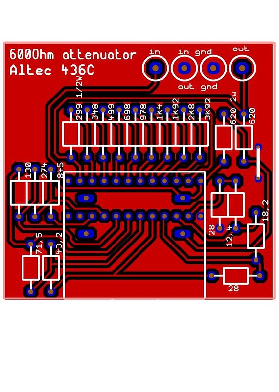
Here is my work in progress:
Schematics with mod included: (attack, release pot, balance trimmer, meter adjust trimmer) Mod are based on NYD's work and recommendation from this thread.
In the schem I haven't included the bridged T output attenuator, but it's easy to setup and it won't be onboard..
http://i251.photobucket.com/albums/gg312/Nadege1509/altec436schemv22BIG.jpg
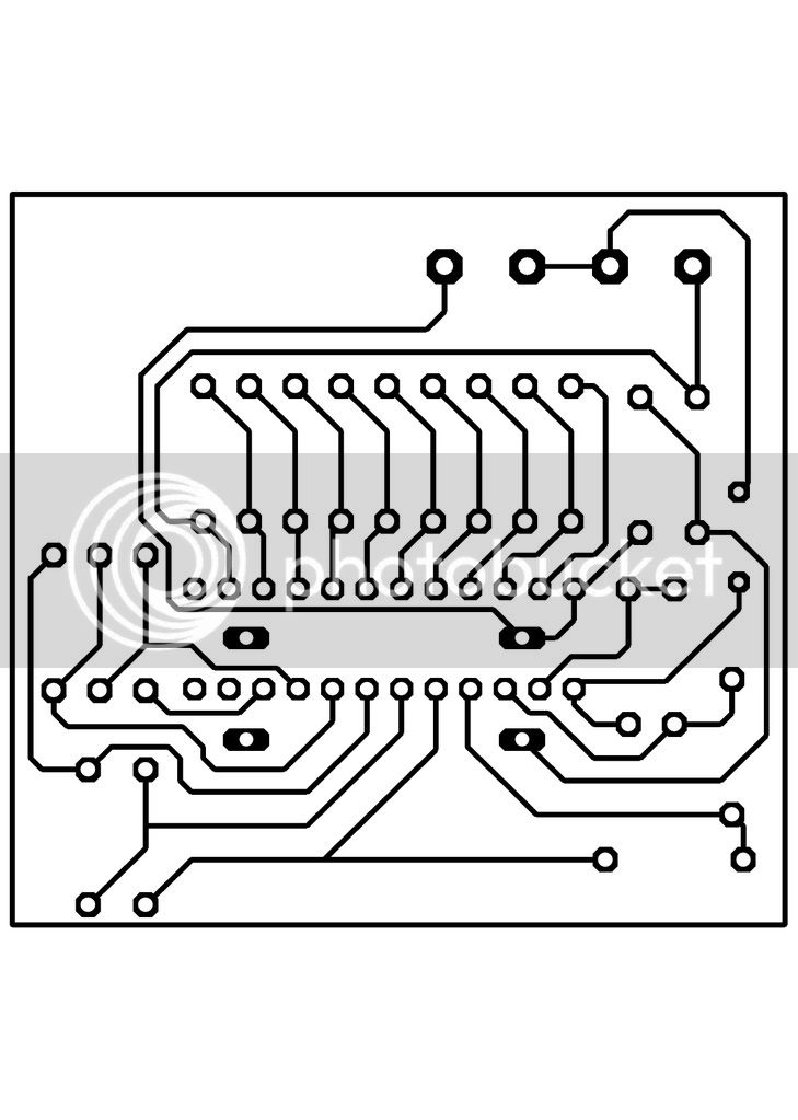
Here is the PCB atrwork: There is two version. One is with one layer( v2.2) but you'll need to wire the heater like on drip's la2 pcb version 1
the other is two layer. (v2.3)
http://i251.photobucket.com/albums/gg312/Nadege1509/altec436PCBv22.jpg
http://i251.photobucket.com/albums/gg312/Nadege1509/altec436PCBv23.jpg
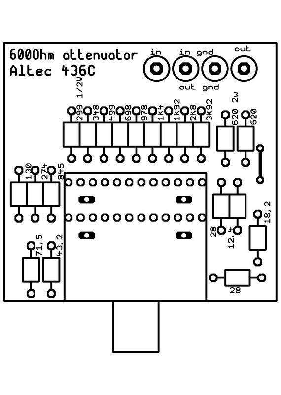
And here is the top and bottom view.
http://i251.photobucket.com/albums/gg312/Nadege1509/altec436PCBTopv23.jpg
http://i251.photobucket.com/albums/gg312/Nadege1509/altec436PCBTopv22.jpg
Let me know . any comments are welcome.
Schematics with mod included: (attack, release pot, balance trimmer, meter adjust trimmer) Mod are based on NYD's work and recommendation from this thread.
In the schem I haven't included the bridged T output attenuator, but it's easy to setup and it won't be onboard..
http://i251.photobucket.com/albums/gg312/Nadege1509/altec436schemv22BIG.jpg
Here is the PCB atrwork: There is two version. One is with one layer( v2.2) but you'll need to wire the heater like on drip's la2 pcb version 1
the other is two layer. (v2.3)
http://i251.photobucket.com/albums/gg312/Nadege1509/altec436PCBv22.jpg
http://i251.photobucket.com/albums/gg312/Nadege1509/altec436PCBv23.jpg
And here is the top and bottom view.
http://i251.photobucket.com/albums/gg312/Nadege1509/altec436PCBTopv23.jpg
http://i251.photobucket.com/albums/gg312/Nadege1509/altec436PCBTopv22.jpg
Let me know . any comments are welcome.
solder_city
Well-known member
i remember nyd posted a schematic of his mods but i cant find it now. is it still online?
solder_city
Well-known member
cool! that would be useful to have for a lot of things, not just an altec 436.
if you look at daves sketch of the attenuator he calculated for a 12th position but didnt use it in the finished design- maybe due to switch availability? but if you have access to a 12 position 2 pole switch maybe you could incorporate it for max atten of 30dB along with 'off'
just an idea.
surprised nyd hasnt made any comment so far. what do you think dave?
abby normal
Well-known member
Looks great! Can anyone confirm that hold feature?
///Edited/// No exact quote anymore, wasn't important anyway. The useful bit is as follows.
They connected a small neon bulb into the audio circuit. Pushing a momentary switch would make it blink three times per second which produced a low freq ticking sound. This was sent to both amplifiers. As one was inverted the ticking would be cancelled out as soon as the the circuit was balanced which was done by turning the balance pot.
They connected a small neon bulb into the audio circuit. Pushing a momentary switch would make it blink three times per second which produced a low freq ticking sound. This was sent to both amplifiers. As one was inverted the ticking would be cancelled out as soon as the the circuit was balanced which was done by turning the balance pot.
solder_city
Well-known member
that thing with the neon sounds like a 'relaxation oscillator.'
but look at the balance adjust note on daves schematic, that could be wired up to a momentary switch. easier to do than putting an oscillator circuit inside the thing. you could do it by ear, listen for the 60 cycle hum and adjust for minimum. right?
but look at the balance adjust note on daves schematic, that could be wired up to a momentary switch. easier to do than putting an oscillator circuit inside the thing. you could do it by ear, listen for the 60 cycle hum and adjust for minimum. right?
abby normal
Well-known member
[quote author="solder_city"]that thing with the neon sounds like a 'relaxation oscillator.'
but look at the balance adjust note on daves schematic, that could be wired up to a momentary switch. easier to do than putting an oscillator circuit inside the thing. you could do it by ear, listen for the 60 cycle hum and adjust for minimum. right?[/quote]
Yeah but the ticking idea is pretty foolproof and it sounds incredibly easy to implement. If you check Dave's folder where that schematic resides there is a note stating that he did not want to drill into his for mods, I would guess that it might have been a reason why he did not add this one and the hold option to the list. Just a guess, maybe Dave might jump in on this?
bcarso
Well-known member
[quote author="abby normal"] Just a guess, maybe Dave might jump in on this?[/quote]
Why am I reminded of the famous joke about Calvin Coolidge?
Why am I reminded of the famous joke about Calvin Coolidge?
abby normal
Well-known member
[quote author="bcarso"][quote author="abby normal"] Just a guess, maybe Dave might jump in on this?[/quote]
Why am I reminded of the famous joke about Calvin Coolidge?[/quote]
Because you're a history major and your living in the past... Lol :razz:
Why am I reminded of the famous joke about Calvin Coolidge?[/quote]
Because you're a history major and your living in the past... Lol :razz:
flaheu
Well-known member
Nadège,
Do you plan to make these little attenuator pcb available ?
Would be cool
Do you plan to make these little attenuator pcb available ?
Would be cool
Hi Guys,
:!:
I've received a formal complaint from the author about the use of quotations from the book "Recording The Beatles" and use of copyrighted material from his website.
Please make sure that the material you use here can be considered within the limits of "fair use"
Jakob E.
:!:
I've received a formal complaint from the author about the use of quotations from the book "Recording The Beatles" and use of copyrighted material from his website.
Please make sure that the material you use here can be considered within the limits of "fair use"
Jakob E.
solder_city
Well-known member
uh oh, grab it now people!
Similar threads
- Replies
- 103
- Views
- 37K