API 312 Thread!

GroupDIY Audio Forum

Help Support GroupDIY Audio Forum:

This site may earn a commission from merchant affiliate links, including eBay, Amazon, and others.
byoung
Jim's JLM 5 rail is a nice PSU board and peterc has a nice on too but....

Fabios PSU board is fine.  If you got one go ahead and use it. I use one in my test bench  PSU.  Just keep the Regulators cool with heatsinks and you will be fine.  I would use a 35VA toroid for good PSU headroom.  :)

BTW...
Don't shy away from the gar2520 DOA kits. ;D ;D  They are fun to put together and sound really nice.

GARY
 
rrs said:
Well almost finished my first API.

Just waiting on opamps from Fabio.  ;D
Wondering what the maximum voltage the OpAmps can take? I've heard of a few people blowing theres and wondering what are the main causes of this???
P1010086.jpg

P1010087.jpg

Hi. Where do I get these boards? I notice there are different PCBs available but I want these. Also does anyone have a complete, verified BOM (w/ mouser/digikey numbers)??
 
I'm selling them. You can check out all the details on the site in my signature. I'm currently out of stock but will be sending out for more soon; I should have more within a month and a half at the most.
 
For any folks following the thread who've expressed interest in my PCBs, I have more in stock and ready to ship. More details if you click on the link in my signature.
 
hello!
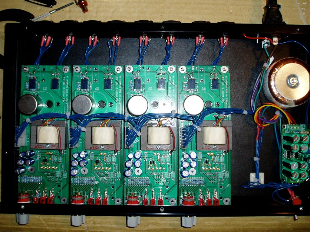
i'm building a unit of 4 api312 with fabio's pcb and jsteiger 2503 and 2622 transformers,
i did a search on the forum to find some informations,
i saw the mods on RPP3 that allow the phantom power to be off immediatly,
on the schematic mods you put a 200R 1W resistor but i have 169R 2,5W 5%(like in fabio's bom) can i use it? or do i need 200R 1W?
thanks everybody!

 
What mods are you talking about? If the 169 or 200r resistors are the only thing in between your +48 and ground you'll end up with 13.6 or 11.5 watts, respectively, through your bleeder resistor. If your 6.81K resistors are in series then you only get 1.2 watts from the remaining voltage across a 169r resistor. If the latter is the case, either value should work fine.

Other people have talked about just putting a higher value r between your PP supply and ground (one that isn't switched), like 30 or 40K. That would probably work fine too.
 
adrian said:
thanks for your answer, so i gonna try with 169R,
the mod i saw is: ..
RPP3 / CPP1 is a simple RC filter set for 3.6Hz with 200R or 4.3Hz with 169R for a more clean 48V rail. This 31R difference won't matter that much and rating at 1W is oversized. This series resistor will slightly drop the 48V, but limit the current of a charged CPP1 cap when phantom voltage is switched off.
If your +48V supply is regulated by a LM317, don't miss the diode (D13 from Fabios psu) between input and output of this regulator. The charged caps value connected to regulator output might exceed the value in front of this chip and these don't like it when powered reverse.
 
thank you guys!
so i tryed my preamp but it's only working with the HiZ input (that isn't using the input transformer),
i checked it and the signal comes to the transformer input pin 1 and 4.
my input transformer is the EA2622 from classicapi... i was thinking it had the good pin configuration for fabio's boards (i'd compared fabio schematics and classicapi datasheet) :

http://www.classicapi.com/catalog/images/gallery/2622/2622-specs.pdf
http://www.thediypill.phx.com.br/forumfiles/R312sch_rev3.pdf

but maybe i'm wrong?!
could it be values of RC and RL resistors that are not good for this transformer?

here are some pictures of my unit:

Voir le Fichier : 100_3719.JPG

Voir le Fichier : 100_3713.JPG

Voir le Fichier : 100_3720.JPG


I tryed it in parallel and everything's ok!
but i saw on this topics that every transformer need a special RC, RL and CC value, how can i find it for the 2622?

 
Since Ed's recreation of the original is supposed to be an exact replica (if I recall correctly) then the zobel should be like the original API:  RC = 5k1, CC = 220pF.

You may want to check with Ed to be sure.
 
kato said:
Since Ed's recreation of the original is supposed to be an exact replica (if I recall correctly) then the zobel should be like the original API:  RC = 5k1, CC = 220pF.

You may want to check with Ed to be sure.
Hey all,

The original schematics for the 312 and for my 536 input channels in my board all show 5.1K and 220pf for the Zobel. In reality, my boards were populated with a 10K R and the 220pf cap. Ed has confirmed the 10K R on the 312 card he used when he was working on the EA2622 design. BTW, suggested load R after the Zobel network is 150K when using a 2622, new or old. 

Also, I have noticed that many of the 312 boards that are in existence these days, don't have the input x-fo primaries in parallel. This must be done with a new or old 2622 for good performance(1:7 ratio). 3nity's Access boards have an optional jumper for this which is cool. Otherwise, just solder a small jumper from pin 1 to pin 2, and another from pin 3 to pin 4 (under the PCB) after the 2622 is solder normally into position.  8)

Best regards, Jeff
 
as you know i'm a newbie,
i was looking for the zobel in fabio's schematic but i don't find it, there seemed not to be anything else than RL, RC and CC between the transformer ouput and the OP1 input... ( http://www.thediypill.phx.com.br/forumfiles/R312sch_rev3.pdf )

i'd searched on wikipedia and what i understood is that it improve the frequency curve l but i don't really understand what is his function here... and if i really need it here etc..

i'm sorry if my questions seemed stupids but i'm very interested to improve my diy knowledge..
thanks everybody!
:)
 
jsteiger said:
Also, I have noticed that many of the 312 boards that are in existence these days, don't have the input x-fo primaries in parallel. This must be done with a new or old 2622 for good performance(1:7 ratio). 3nity's Access boards have an optional jumper for this which is cool. Otherwise, just solder a small jumper from pin 1 to pin 2, and another from pin 3 to pin 4 (under the PCB) after the 2622 is solder normally into position.  8)

Best regards, Jeff

Jeff, I just picked up a couple of 3nity's last remaining access 312's.  I also bought 2622's and 2503's from you.  There was a good deal of info in the access312 thread in the white market, but since they're all sold now that thread is gone. 
I remember you mentioned (as above) about jumpering the input trafo primary, but I also seem to remember some talk about other component changes using your iron with 3nity's board.  Am I imagining this, or were there indeed resistor/cap value changes?
Thanks!  Sorry if I'm remembering this wrong!
 
wire the trafo primaries in parallel as jeff says, and use whatever Ed recommends for load R and zobel. this should be on jeff's site.
 
He guys,

Use 1000pf for decoupling before the 2622 primaries. One on the Hi side and one on the Lo side. Primaries should be in parallel as previously noted. Recommended Zobel is 220pf and 10K R. The load R after the Zobel should be 150K.

This will pretty much get you where you want to be.

Best, Jeff
 
Back
Top