API 312 Thread!

GroupDIY Audio Forum

Help Support GroupDIY Audio Forum:

This site may earn a commission from merchant affiliate links, including eBay, Amazon, and others.
Did you get an answer on dropping in the NE5534 as a direct replacement for the 2520 without any extra modifications?

 
Hi all.
Hoping someone can help me out with a problem with one of my API 312 (Bob's Hybrid boards). Sound great too by the way using Ed Anderson's trannies.

I have built 8 of these but one is giving me greif.

The problem being that 48V dosn't seem to be getting through to the (Input XLR) for phantom power.
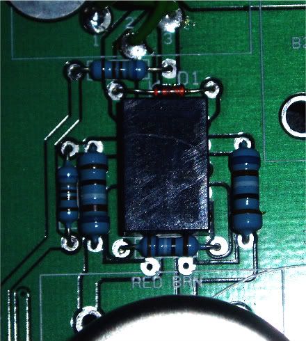
I have 48V at one end of R26 and the other end is 42V, I then have 42V at next point being R27 but 0V on the other side. 0v on input XLR pins also.
So I have gone a while without 48V and thought it would be ok but then the channel wouldn't work altogether (no 15v). I replaced a few parts and seem to have the 15v back but still no go with the 48V.

I have replaced D1,2 and R26,27,28 .

Any advice??
 
The best I could say would just be tocheck continuity from your DC inputs on the board all the way to their destinations. Check the same for ground paths, and make sure you have continuity between the ground terminals of the terminal block and your audio ground.

It seems like there's probably a break in continuity somewhere, tracing the supply and return paths should show where any issues are.
 
Sorry guys i'm really struggling with this. Probably mainly to my lack of electronics understanding.

I have the channel working again but still 48V not getting to XLR inputs and disappearing after the R27,R28 resistors just before the input. All other channels working fine and wired up the same.

Anyone know what can cause this ??
 
For sure. You just need to figure out why that is the case. I'd start by double checking the values of R27, R28, and R26, and while you're at it you could just make sure that C15 value is normal and that it's not passing DC.
 
If you are dropping 6V across R26 then you have 12(ish)mA flowing through it, and so 6 mA through each of R27 and R28.
Therefore you have a short to earth somewhere around R1/R2 RL1 or T1. But you say you have 65 or 70 Ohms when measured on the XLR to earth. Sound like the centre tap of T1 is connected to earth!
 
bobschwenkler said:
Oh, do you have a spacer of some sort underneath your input transformer? If not, you might be shorting out some of its pins.
Good call Bob. Could be the cause?
 
RE: Input transformer (EA2622) there is no spacer but a good 2 or 3mm gap between it and the PCB. Looking from the side there is absolutely no contact with the PCB.
Side Pic
P1010181-1.jpg

Underneath Pic.
P1010182.jpg

Top Pic.
P1010181-2.jpg
 
Well I think you might have to spend a bit of time poking around looking for shorts. It's conceivable that there is a short in one of the traces from the manufacturing process. The place I went with seems to have been pretty good, but I did have one board with a short (in a non-critical location).

Good previous point about the center tap being shorted. I don't know what the DCR of these primaries is, but it could easily be around 70 ohms. You might work on isolating the issue by removing or lifting one leg of components and keep working that way til you pin it down.
 
bobschwenkler said:
...I don't know what the DCR of these primaries is, but it could easily be around 70 ohms...
It's in the area of 55-60 ohms and about half of that when the primaries are in parallel. FWIW, the secondary should be about 1K6.

Jeff
 
Thanks for the help guys.

Solved the problem. The bridge between pin 2 and 3 seemed to be shorting to ground. Disconnected to test which pin and no short. Reconnected and seemed fine.
Don't know exactly what happened but all working now.
 

Latest posts

Back
Top