Bypass relay PCB: available

GroupDIY Audio Forum

Help Support GroupDIY Audio Forum:

This site may earn a commission from merchant affiliate links, including eBay, Amazon, and others.
Hello, this is my first post on this forum.
Is there anyone that can help me to understand which values I need to get for the Zobel network in the Bypass pcb:

*R_L    *CZ   *RZ

The Bypass is going to link the output of the SRPP stage of the DUAL EQP1A of Gyraf Audio which I have equipped with 2 LUNDAHL LL5402 Transformers (the scheme below) to the XLR IN and OUT of a Dual Eqp1A.

Thanks for your help

Marco

SRPP_1.jpg

 
Hello!
As I can see there is no zobel network at the secondaries of LL5402 in Gyraf's schematics! Consequently you don't need R_L, CZ, RZ at all  ;)
 
Thank you very much for your help, I'm a real dummy with electronics, but I like to build things that sound good...
So I go straight to link as is.
I just have a very little hum (almost imperceptible) which raise when a cable is closer to the valves, I thought at first I could solve with this circuit, I'll check better ground links.

Thank you much

Marco

 
Can I get a BOM or parts list for the bypass PCB? I'm not savvy enough to be able to look at a schematic and know exactly what parts I need unfortunately, so any kind of kit/project setup would be awesome.

TOTALLY depends  on your application.

You need 2x DPDT DIP-16 relays, with high coil resistance, for low power consumption,
solder wires to PCB, a switch, 1N4002 kinda diode, and, probably, if you need light when ON, a LED and resistor.

Relay's voltage:

EXAMPLE1:  if this goes to GSSL, you have about 42...50V between power supply capacitors right after rectifier,
than, I'd use 2x24V relays in series.
Possible to hook to +22 right after diode rectifier and gnd, and use 2x12V in series, but it is less funny imho.

EXAMPLE2: If I have +5V supply inside of a unit I need to hardwarebypass, I use 2x5V relays in parallel connection.
Same about +12V: 2x12V relays in parallel; BTW, here possible to use 2x5V relays with coils in series.

Termination and proper load/Zobel for your trannies: search NET for trafo datasheet etc. I have to do same to answer.
In general, "the way" is.
IF your unit have an output transformer and it IS unterminated and have no Zobel network, bypass PCB allows to put it here.
RL: in general, 600R.....3k for most of trafo's. Rz, Cz: depends on transformer.
Search this forum about how to figure out Zobel network. I saw it 10 times at least described better than I may do.
Scope, square wave, some resistors and some caps to try, 10 min, done.
No scope and square wave oscillator? Search net, maybe, somebody had this experience with this transformer.
In 75% of situations, it is enough right load resistor and NO Zobel network at all.

If you have el. balanced out, forget about all this load/zobel stuff.

Great post about API out transformers terminating BTW:
http://recforums.prosoundweb.com/index.php/m/118457/0/


Hello everyone!
I have a newbe question and will be very thankfull if you help me  :)
According to attached schematics bypass board requires +/-12 or +/-24 V for relays. But for example if I'm building an EQ based on BA283 (which requires +24/0 V) can I use the same PSU for both of them (I mean bypass board and BA283 board)?? And consequently connect "negative terminal" (V_REL-2) of the bypass board to "earth" terminal on the PSU? Or maybe the most preferable variant is to have two separate PSU's?

Welcome! You can use 2x12 v relays in series or 2x24v relays in parallel. Hook V_REL to 24V, - to gnd and + to +24V of you audio PSU.

Is there anyone that can help me to understand which values I need to get for the Zobel network in the Bypass pcb:

*R_L    *CZ  *RZ

The Bypass is going to link the output of the SRPP stage of the DUAL EQP1A of Gyraf Audio which I have equipped with 2 LUNDAHL LL5402 Transformers (the scheme below) to the XLR IN and OUT of a Dual Eqp1A.


As I can see there is no zobel network at the secondaries of LL5402 in Gyraf's schematics! Consequently you don't need R_L, CZ, RZ at all 

In general: you just have to load the out of your trafo with proper resistor. Feed square wave to the input of your SRPP,
get out BEFORE the SRPP clips, load treafo with 10k pot, and see what happens with overshoot. I think, for this kinda circuit, less termination is better. IMHO, no need Zobel. If overshoot is more than 10%, use 200R....1k+4n7....10n, something in this range I guess should work.

DOCS:

http://ij-audio.com/downloads/BYPASS.zip
 
Hi igor,

I'll do GSSL, my first DIY. I'm going to use OAE or similar switch, purusha case and I want to do a bypass. Which of your boards should I use? one or two?

Thanks
Hugo
 
2x 60mm bypass boards, 4x24V relays. Relays in parallel SERIES connection, take relay's voltage right after rectifier (+ and - of big electrolitic caps).
 
Sorry, TYPO. 24 V relays are in SERIES connection.
+32 degrees Celsius outside, 70-75% humidity, the brain is melting down.
 
Hi,

24V relay in serie or 12V relay  in serie? I see in this post:

"Para GSSL, 2 placas necessárias. With 12v relays, I'd connect both boards in series, Com relés 12v, eu ligar ambas as placas em série,
relays wired in series, beetween + and - before 15 V regulators. relés ligados em série, beetween + e - antes de 15 de reguladores V."

thanks
Hugo
 
Both possible. Take voltage between star ground and + of big el. cap of power supply and use 2x12 in series.
Or, take 2x24 in series and take voltage from + and - of of big el. caps of power supply. If using google translate, Russian please! :D
 
Mmm... Same 'bout me. The common thing here is audio and sound. Cool thing, we can understand each other!
 
Igor said:
Hi, what 3 pin set do you talking about? There's IN, OUT, and BYPASS SW...
You mean, ALL Molex connectors are missing?

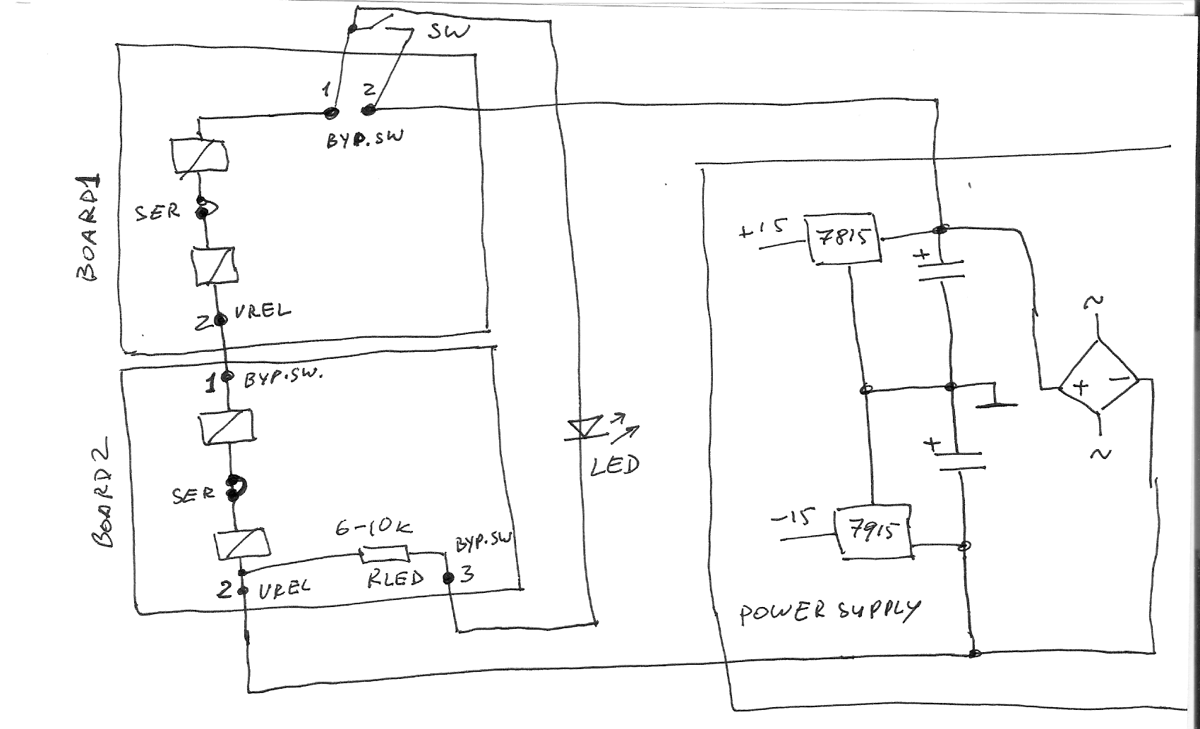
For GSSL, 2 boards needed. With 12v relays, I'd connect both boards in series,
relays wired in series, beetween + and - before 15 V regulators.

Schem:

ssl_byp.gif

Hey Igor I followed your schematic exactly here, with AXICOM 12v relays in series that you recommended... and it works fine except the LED action is reversed to what I would expect... I would expect the LED to come on when the bypass is engaged right?

when my led is on the xlr's feed straight through to the molex headers (bypass off), when the led is off the xlrs are connected directly IN to OUT and there is no continuity on the headers (bypass on).

Any ideas?
 
:(

Hi Igor,

i've sent you two e mails. Ordered and payed via pay pal two relay bypass PCBs  12. June.

Haven't got any answer and no pcbs.!!

Please fix  this as soon as possible.


Erich T.

 
Well, I think, this is not "support" thread, because why board with few components (relays/connectors) should have build support, at all ;)
A bit out of topic - shipping related questions please here:
http://www.groupdiy.com/index.php?topic=29771
When I will do the revolution, first I will take care on all post offices over the world.
For now, regular registered airmail arrives within 2-4 weeks worldwide. We ship every week, so...here it is.
 
Hello, i am not quite sure how to wire this board into the d-aoc, and would really appreciate some help as i cant quite get it working. Everything populated except for byp-switch, and v_rel 1&2. Im using a regular DPDT toggle on each of the 2ch.'s with no bypass LED's. 24v relays in parallel with 24v pwr. What is best way to wire up? The psu board has a 24v reg for this and i have the associated 2pin molex going to a terminal strip so I can send the power everywhere I need it [ VU's and bypass boards ]. So, not sure the right way to get dpdt hooked up to pcb's. Also, what is v_rel2 for, and on the in/out molex i only used 2 wires to 1 &3 as it was coming from output xfmr sec. Is this ok? What to do with middle gnd pin? Is it the same on the byp_switch molex? Damn, thAats a lot of stuff. Forgive me.  Thank you as always for your help. All the best,
                                                                                                                                                ----Joseph
 
So, I got everything working as it should be. Trial & error, error, error, trial........pass! Sorry to bother with a question I ended up answering with just sticking with it a while longer. Thanks again for the great boards. All the best.  ----Joseph---- BA&E
 
Hi,

I'd like to use the Bypass PCB for my stereo Pultec but please who can me what is it on the picture ??!! :)
Is this the relay ??
 

Attachments

  • cquoicetruc.jpg
    cquoicetruc.jpg
    37.3 KB · Views: 47

Latest posts

Back
Top