livingnote
Well-known member
Thanks


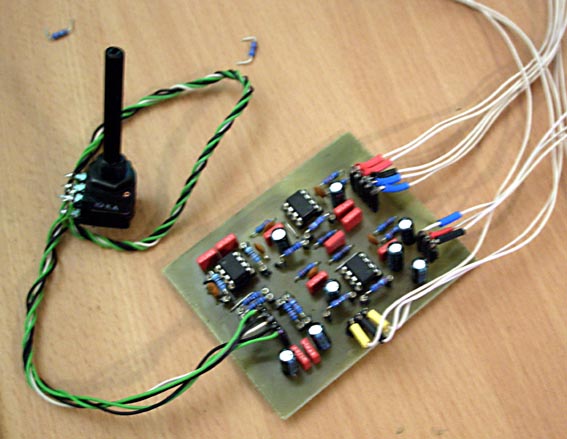
dagoose said:About the potmeter, pin 3 is ground but where do pin 1, 2, 4 and 5 connect to exactly on the pot?
")
dagoose said:ok... i now know what the not mentioned holes are... something like a 0.000000r resistor... in other terms.. jumper.. ;D
livingnote said:Yah weird, that is. So your implant worked right, and when you pull the chips it works, but even when you swap ICs the same channel is screwed? I really wonder what it could be, really sounds like some cap would be shorting the high stuff to ground, but then what you should be getting is the missing high end with chips pulled, too...
Might I suggest you build the other one too and then just see if the problem is in the system itself? I mean, I got the exact same one working lovely, produced 3 CDs through it, not a hitch...
Enter your email address to join: