


Hey guys,
As some of you may know, I am currently in the process of designing a passive EQ. I got some pot cores and some enamel-coated wire a while ago, and today I spent a good 4 or 5 hours playing with them. So here's some observations:
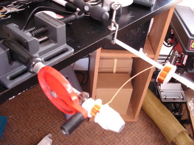
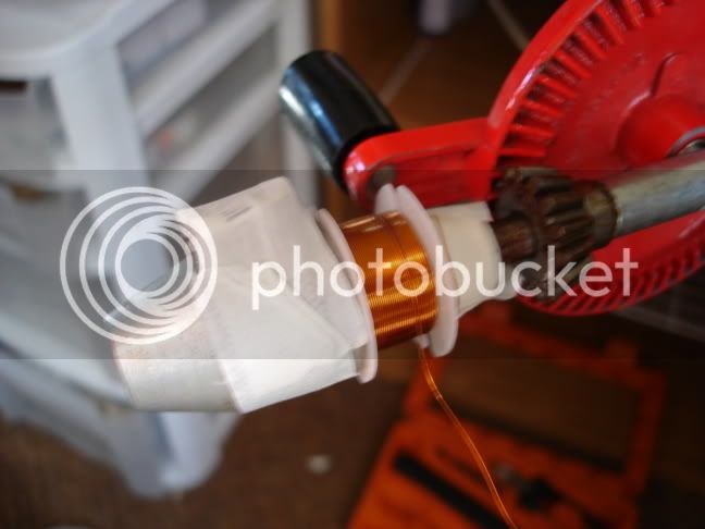
I worked on my EQ's low band inductor, which is a 1.64H little monster, with taps at 490mH and 820mH. I used a 3622 core from Amidon, which comes with a plastic bobbin, and a plastic screw and nut. I looked at the wire-gauge vs. number-of-turns chart on Amidon's website, and determined I could use 29-gauge wire, so I got some also from Amidon. It came out just right - 50 more turns or so, and the bobbin couldn't have held all the wire.
The first thing anyone winding coils on the Amidon sets needs to be aware of, is that the tightness of the plastic screw/nut changes the inductance of the coil significantly! I kept getting readings that were all over the place, and finally realized that the screw tension was to blame. It's kind of annoying, but it may actually be a good thing, since it allows you to fine tune the inductance of a coil without having to take it apart to take off turns...
For measuring inductance, I built myself a little resistance decade box and used this setup:
The measuring process goes like this:
1. Set the signal generator to whatever frequency the inductor will work at, and set the generator's amplitude to 4Vp-p (I chose 4Vp-p because it's easy to work with. I didn't see any difference at all with voltages as low as 100mV, or as high as 10.5Vp-p, which is the limit of my signal source).
2. Put a scope probe across resistance box, and increment the resistance until signal on scope is exactly 2Vp-p.
3. Read the value from decade box - this value is the inductor's impedance at that particular frequency.
4. Measure the DCR of the inductor, and figure out the inductive reactance (XL) of the coil by re-arranging the formula Z = sqrt(DCR^2 + XL^2).
5. Finally, figure out the inductance (L) of the coil by re-arranging the formula XL=2pi*f*L.
I ended up with something like 300 turns for 490mH, an extra 115 turns to get to 820mH, and a final 150 turns to reach 1.64H. Total: ~565 turns, 12 Ohms of DCR. Not bad at all!
Damn! 4:30AM... :?
I'll keep working on this tomorrow...
Peace,
Al.
As some of you may know, I am currently in the process of designing a passive EQ. I got some pot cores and some enamel-coated wire a while ago, and today I spent a good 4 or 5 hours playing with them. So here's some observations:
I worked on my EQ's low band inductor, which is a 1.64H little monster, with taps at 490mH and 820mH. I used a 3622 core from Amidon, which comes with a plastic bobbin, and a plastic screw and nut. I looked at the wire-gauge vs. number-of-turns chart on Amidon's website, and determined I could use 29-gauge wire, so I got some also from Amidon. It came out just right - 50 more turns or so, and the bobbin couldn't have held all the wire.
The first thing anyone winding coils on the Amidon sets needs to be aware of, is that the tightness of the plastic screw/nut changes the inductance of the coil significantly! I kept getting readings that were all over the place, and finally realized that the screw tension was to blame. It's kind of annoying, but it may actually be a good thing, since it allows you to fine tune the inductance of a coil without having to take it apart to take off turns...
For measuring inductance, I built myself a little resistance decade box and used this setup:
The measuring process goes like this:
1. Set the signal generator to whatever frequency the inductor will work at, and set the generator's amplitude to 4Vp-p (I chose 4Vp-p because it's easy to work with. I didn't see any difference at all with voltages as low as 100mV, or as high as 10.5Vp-p, which is the limit of my signal source).
2. Put a scope probe across resistance box, and increment the resistance until signal on scope is exactly 2Vp-p.
3. Read the value from decade box - this value is the inductor's impedance at that particular frequency.
4. Measure the DCR of the inductor, and figure out the inductive reactance (XL) of the coil by re-arranging the formula Z = sqrt(DCR^2 + XL^2).
5. Finally, figure out the inductance (L) of the coil by re-arranging the formula XL=2pi*f*L.
I ended up with something like 300 turns for 490mH, an extra 115 turns to get to 820mH, and a final 150 turns to reach 1.64H. Total: ~565 turns, 12 Ohms of DCR. Not bad at all!
Damn! 4:30AM... :?
I'll keep working on this tomorrow...
Peace,
Al.
 ...
...