Newbie builds GroupDIY 51X rack

GroupDIY Audio Forum

Help Support GroupDIY Audio Forum:

This site may earn a commission from merchant affiliate links, including eBay, Amazon, and others.
rob61 said:
I think I just made my first mistake. I mounted the 350's to the ps mother board as indicated by the printing on the circuit board. So with the heat sinks included in my kit. do I mount the 350s to the heat sinks instead of the mb, and then run extender wires from the pins to the ps mother board?

Yes, that would be correct.
 
Hey guys,

A bit of a wait for PSU parts to come in, but my package from Jeff came in today while I was at work.  A little housekeeping. . . while this thread is probably visited from time to time by experienced folks, technical questions about the official DIY rack and PSU should be directed to the official support thread.  Those threads are constantly monitored by the people who designed the kit, and they will be able to get you an accurate, timely answer to build details as well as assist with trouble shooting.  I'm just a newbie with a soldering iron who happens to know how to take pictures.

That being said, this is America. . . post what you want!  ;D ;D well. . . I'm not sure if the server is physically in America.  Anyways, I know there may be quite a few people watching this thread for step-by-step build information, and I'm on it.  Just WAY too zonked tonight to be driving a soldering iron.  Events at work today had me shooting stills and video for 12 hours, and last night was 2:00AM lugging equipment and setting up.

But, my parts are here!  Let's rock.

p939911352-4.jpg
 
Let's do this thing. . .

p597830303-4.jpg


The first thought that crossed my mind when unpacking the box was, well. . . am I ever going to get to the actual parts?  jsteiger packed everything really well.  Despite UPS's best efforts to damage the parts, everything came in just fine.  Excellent!

My 2nd impression was, "Are you kidding me?  This stuff is absolutely gorgeous!"  I'm not an experienced electronics guy by any stretch of the imagination, but I can tell when something is well thought out or highly functional, but this kit goes well beyond those metrics and I get the impression it is a point of pride for the guys who put it together.  Simply uncompromising in every detail.  What an absolute treat to assemble.

I don't even need to take pictures because the chassis is so easy this time 'round, but I'm going to post a ton of them because folks need to see this stuff to believe it.

Alright. . . it's really hard to get this case wrong, but I'll do my best. . .  ;D fish these 2 pieces (back and side)out of the pile.

p703243624-4.jpg


There is only one type of beveled machine screw for this case, and they come packed in a baggie like this:

p890701392-4.jpg


first gratuitous photo. . . threaded inserts for machine screws?  There's all kinds of awesome sauce going on here.

p1065555640-4.jpg


Put the two pieces together at the corner. . .

p663848541-4.jpg


And then screw together.  Holes are self aligning, so I went ahead and torqued them down.

p566462179-4.jpg


Same procedure for the opposite side panel.

p1009175876-4.jpg


Then, find the front face and marvel for a bit.

p803227064-4.jpg


p957155167-4.jpg


Make sure to position the hole for the Neutrik connector behind the "48V" marking, and the large square cutout behind the power switch location.

p667420645-4.jpg


And screw the front panel in with 4 screws.

p927973532-5.jpg


Then, locate the bottom panel. . . and again, marvel at the details. .

p990438956-4.jpg


p1039521606-4.jpg


The standoffs are built into the panel. . . super cool. . . back side of the standoffs:

p857018743-4.jpg


Flip the case upside down, and place the bottom panel.  Align the divot for the toroid on the "power switch" side of the case.

p656512973-4.jpg


And. . . apply screws

p592015792-4.jpg


And, voila!  One power supply case.  Now, it is incumbent upon me to make the insides look just as nice as the outsides.  That's a tall order, but I'll certainly give it my best effort!  Seriously, the GDIY team has really outdone themselves on this.

p748334795-4.jpg


p728398146-4.jpg


p807177456-4.jpg


p690762885-4.jpg


Alright. . . we're back on track. . . Next, I'm going to attempt to stuff the PSU without mucking it up too badly.  The first thing I do is identify and sort the components.  Being as my diagnostic skills are not quite up to par, I put a premium on not mixing up the pieces and getting it right the first time.  To that end, here is what I do:

I make a little card identifying the parts. .. for resistors, I sort by color code and by testing on multimeter.  I re-use the cards when I build another one.  For this PSU, I will be doing at least one more.
p538844373-4.jpg


p852192983-4.jpg


here are the electrolytics:
p924465595-4.jpg


p833561488-4.jpg


All of the ceramic caps on this PSU are the same:

p807123971-4.jpg


As well as the film caps:
p987881764-4.jpg


and. . .the cat wants to help a bit. ..

p910057007-4.jpg


Note, there are 2 types of IC's. . .

This is IC1 for the 48V

p997245027-4.jpg


and this is IC11, IC21, IC31, and IC41 for the other voltages:
p542911110-4.jpg


Here are the 1K trimmer pots:
p846054936-4.jpg


And the B80R diode (BR1)
p543734933-4.jpg


Now that I have my parts identified and sorted, I can start stuffing the PCB.  I've found it sometimes helpful to look at the PCB and stuff it from the "shortest" components to the "tallest".  That way, I have a good chance of easily reaching everything I'm installing.  I'm sure there are many correct ways to install the parts.  This is just how I did it, and it worked fine.  So, I started out by putting in the resistors.

p715049885-4.jpg


And then, the small diodes:
p867381144-4.jpg


Next, I went for the ceramic caps and the BR1 diode. . . Note the markings on the PCB ~ and + to position BR1.  They correlate with the markings on the part.

p710902455-4.jpg


p543734933-4.jpg


And, ceramics and short diodes are in:

p781618068-4.jpg


Next, I installed the film caps:
p596423065-4.jpg


Then, the terminal blocks and trimmer pots:
p663973303-4.jpg


Then, I installed diodes BR11, BR21, BR31, and BR41. . . the tall ones. .. as well as some of the electrolytics.  The electrolytics have polarity, so please note the side of the cylinder with the large line and "-" signs inside.  This is the "-" side of the capacitor.  Also, the longer leg corresponds to the "+" side of the capacitor.  The PCB is marked with a "+" to indicate the correct polarity.
p973713811-4.jpg


2 more electrolytics:
p586748227-4.jpg


And then, I went ahead and prepped the heat sink and IC1. .  . make sure to use the plastic insulating washer as well as the insulating pad.  Test to make sure there is no continuity between the mounting screw and the metal face of the component.

p846973217-4.jpg


After the part is secured to the heat sink. . . I soldered both to the PCB
p58277040-4.jpg


Next, I installed the 4  large electrolytics.
p141019140-4.jpg


And, at this point, the PSU is stuffed with the exception of the regulators for the 4 main voltages that will mount to the large heat sinks and get jumpered into the PCB by wires.

p385333001-4.jpg


Humans win!


Your cat is more like: "Should i eat the blue or the red pill...." haha, sorry for polluting, anyway just looking at the pics i can see that the PSU is Top Notch, Hats off to the Alliance and Cemal...
 
Next, I needed to figure out how to wire everything together inside the case. . . All of the necessary information is available on the official support thread.  Much of it is a bit confusing to me, so i decided to make myself a little road map of all of the PSU internal wiring to sort it all out in my head prior to diving in.  Please note, the colors indicated on the Toroid correspond to the unit jsteiger supplies to kit builders in the United States.  If you purchased your kit from a different source, your color scheme may be different.  Because of this, I tried in my sort of "semi-literate" fashion to indicate primary and secondary windings on the toroid so that this map can be translated to a different toroid without much hassle.  For the folks who actually know what they're doing, please let me know as soon as possible if you spot a mistake in this map.  I don't want to mis-lead anyone into a potentially hazardous situation especially wiring mains.  Another point that was not crystal clear to me was how to wire the LED's on the front panel.  I hope that I got the cathode and anode sides correct with positive and negative voltages that we are supplying.  Note, there is a long leg and a short leg on each of the little LED drawings.

p177104910-5.jpg

 
'Chung

All looks very good and right on the money to me. Nice work. I think I will be sharing a link to this post many times.  :)

I predict if you execute your "road map" as drawn, you will have much success and not harm yourself, anyone else or any of your components.  ;D  If I am wrong, I shall be held harmless :)

Have fun with it!

Best, Jeff
 
Sorry for the delays. . . for those who have been waiting on this as an "instructional" thread.  I figured with the map done, all of the information is contained in this thread for folks to complete the PSU.

But, onward with my build.  A little progress at a time.

First, I prepped the heat-sink mounted regulators for installation.  I felt these connections would be very difficult to solder after mounting in their final positions, so I did them flat on the bench.

p287700903-4.jpg


There is no rhyme or reason to my color choices.  I just wanted to keep it consistent so I don't reverse them when soldering to the PCB.

And, a bit of shrink wrap:

p375506617-4.jpg


Next, I mounted to the heat sinks and bent the tabs 90 degrees for the wires to clear the case.  I'm not sure if I got the order correct for the washers, nuts, and lock washer, but this seemed to work just fine.  Just make sure the insulating washer is installed properly and there is no continuity between the screw and the silver tab of the transistors.

p145061113-4.jpg


These are the screws used to mount the heat sinks to the case.  Notice the threads are slightly tapered.  The holds drilled in the heat sink are not threaded, and these screws kindof self-tap a bit as they go in, so be careful to apply enough downward pressure with the screwdriver and not strip them.

p485502316-4.jpg


p138313812-4.jpg


And, here I am for now. . .

p114705425-4.jpg


p505444123-4.jpg
 
OK. . . last push. . .

Here, the voltage regulator leads are soldered into the PCB.

p555086604-4.jpg


With all components electronic connected on the PCB itself, I move to the A/C side. . . 1st step, figure out what orientation to put the toroid.

p873785323-4.jpg


Toroid is located:

p866738391-4.jpg


Next, I looked for the most difficult to reach connectors, and started hooking up there because these leads would be extremely hard to reach later.  Following my map, I proceed as such with the 240/120 voltage selector switch:

p737259513-5.jpg


p594636186-5.jpg


And, the A/C side is complete. . . the board powered up, and I was able to test and trim voltages.  There were a few more safety items (connector sleeves and such) included in the kit that I did not utilize because I felt some of them would have potential to crowd the connectors when installed, and sometimes the exposed leads are dangerous, but I'd rather be able to see them to visually verify that things are proper.  Personal choice.  Please remember to disconnect the power cord at this point after trimming voltages or doing other diagnostics before diving back in!!!

p1018874573-4.jpg


For now, here's where I'm at :)

p690660789-4.jpg


Next up, hooking up the DC side. . .

 
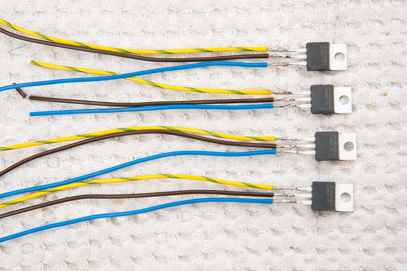
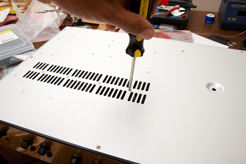
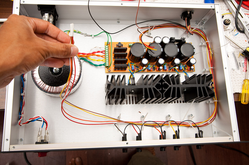
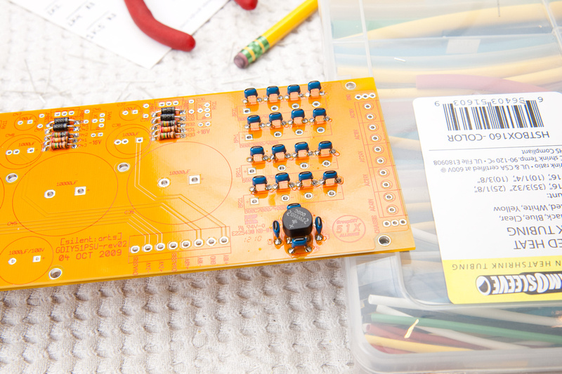
For the DC side, again, I took a look to see if I could identify the most difficult solder joints and start from there while I have access.

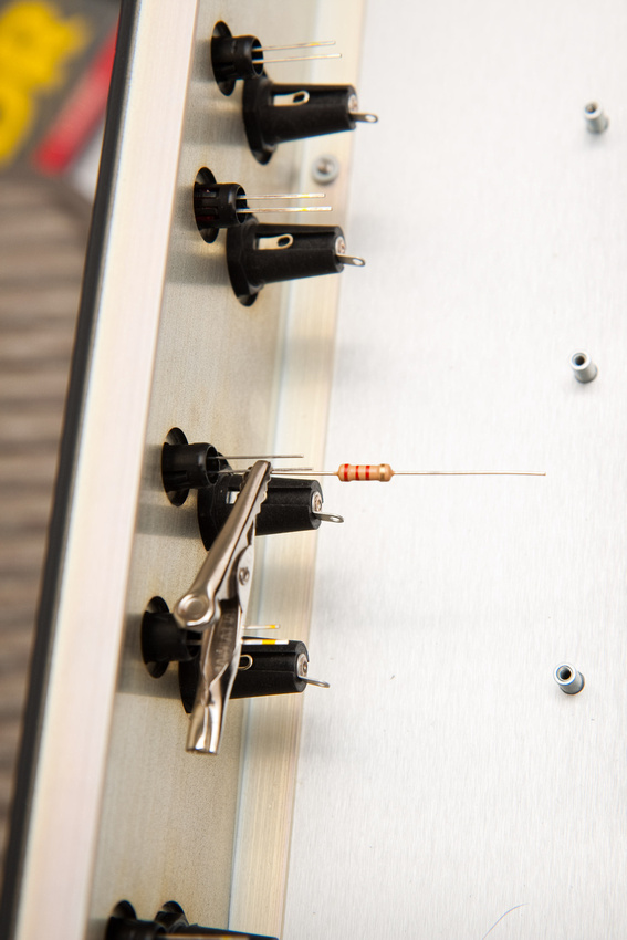
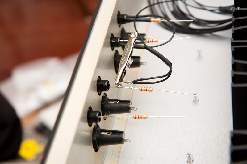
I went with attaching resistors to the LED leads first.  After thinking about it for a little while, this is the method I came up with.  I'm sure there are hundreds of correct ways to do it.  Note, I tried testing the LED polarities first by connecting directly to the +16v and ground from the PCB, and the result was a very bright LED for a second, and then a very dead LED.  Newbie me didn't know that you had to have the proper resistor in place.  Luckily, I had a spare LED, so I threw that in without problem.

Note on LED resistors. . . in order to not buy extra resistors, the 5 resistors used for the LED's should not be populated on the PCB, but used on the the external LED's.  Because I had very little understanding of the PCB when assembling, I just fully populated it.  So, because I had ptownkid's kit on hand that I was not going to use in a PSU build, I used the resistors for the external LED's, and also installed the provided LED's internally on the PCB, so I could have shiny green lights inside  ;D.

p718244101-5.jpg


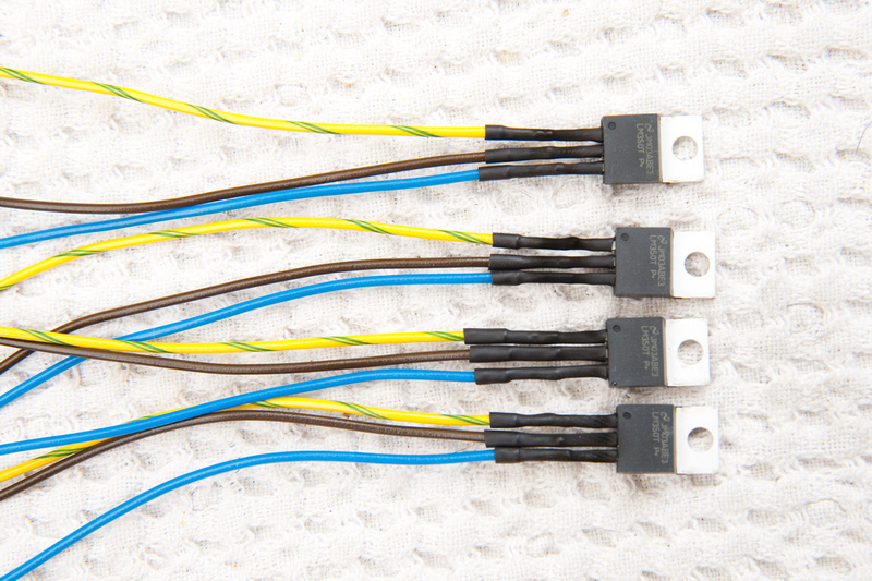
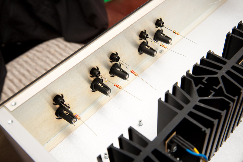
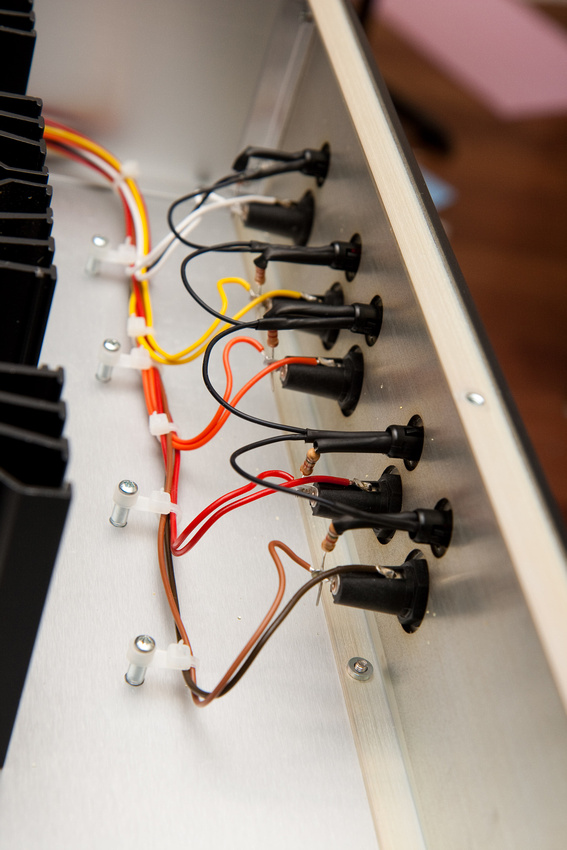
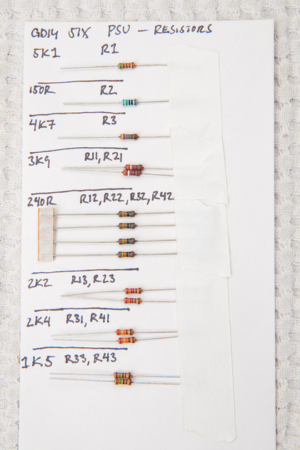
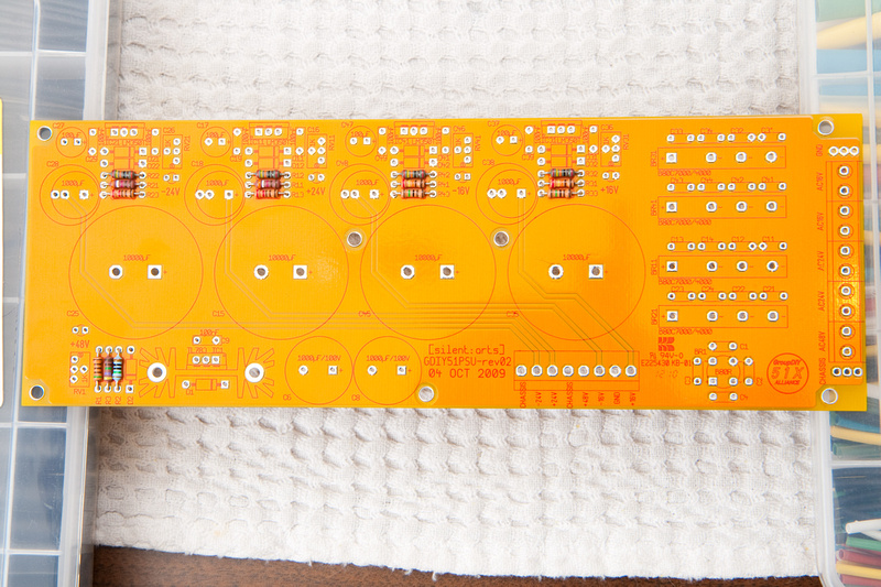
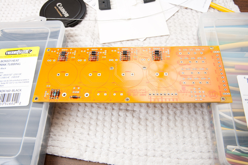
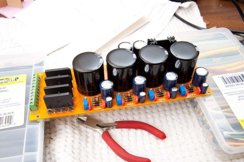
And, resistors are in:

p814425623-4.jpg


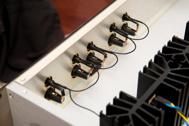
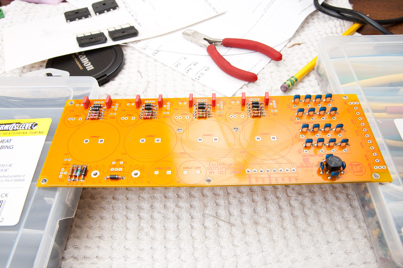
Next I went after the ground connections on the indicator LED's, and the methodology is similar.  I found that the solder does not stick to the alligator clamp.

p1002582063-4.jpg


And, ground leads are in. . .

p734675859-4.jpg


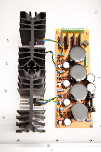
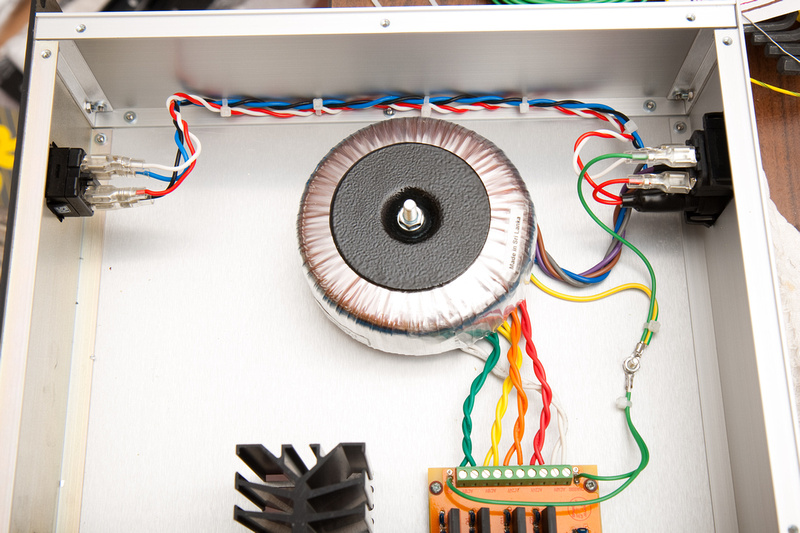
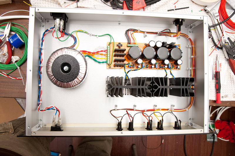
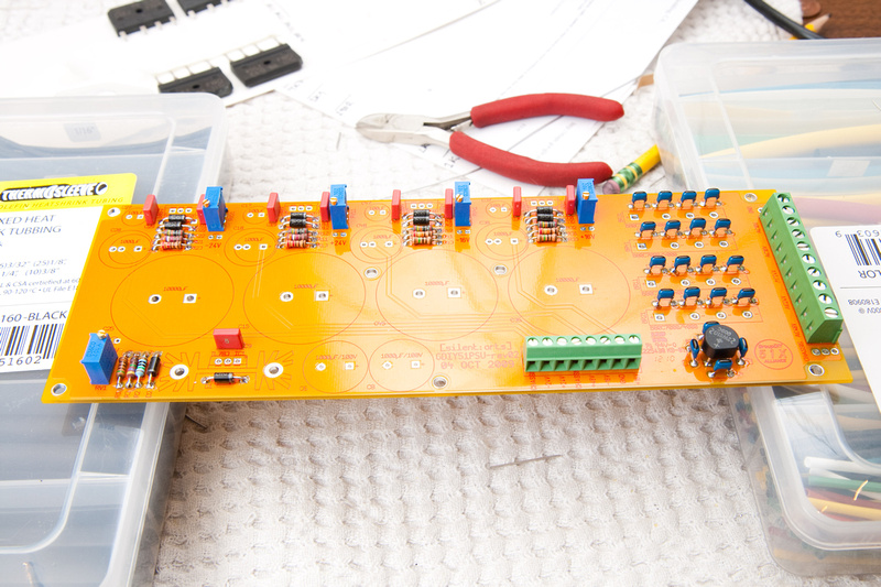
Next, I installed the cable control ties loosely and soldered in the input side of the fuses. . . and threaded the wires through towards the PCB DC outputs.  I used some additional cable ties to clean up the run starting from the fuse side and working my way to the PCB side.  I then cut off my excess cable with a bit of slack to spare at the PCB side.

p953500084-4.jpg


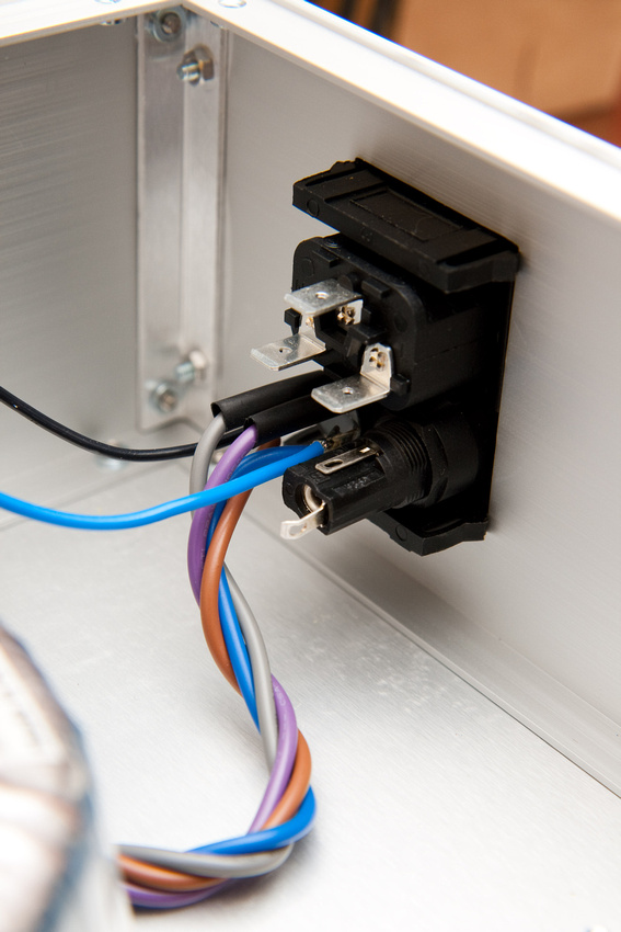
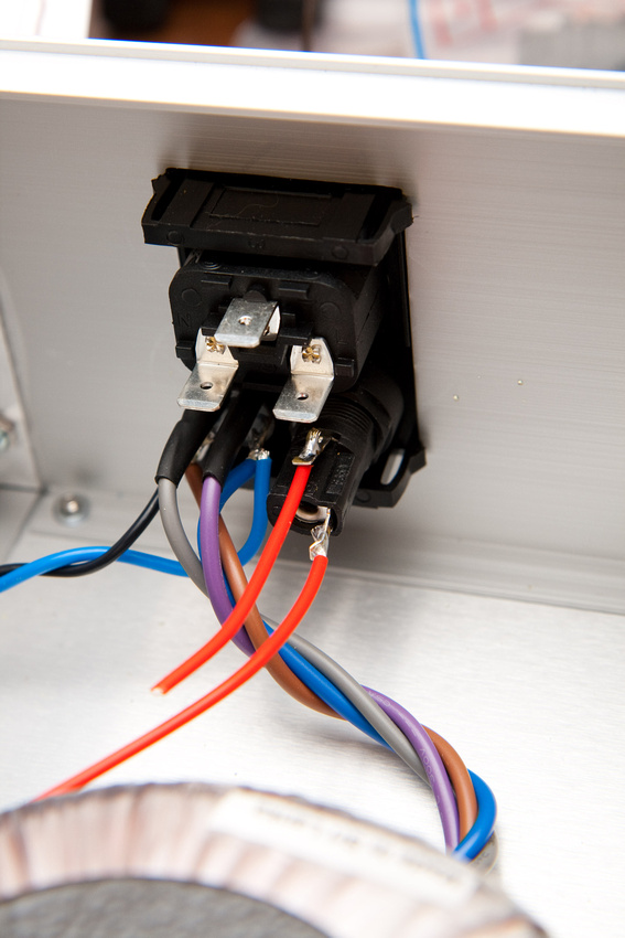
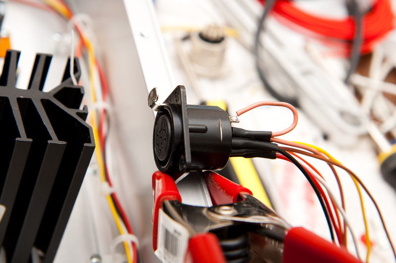
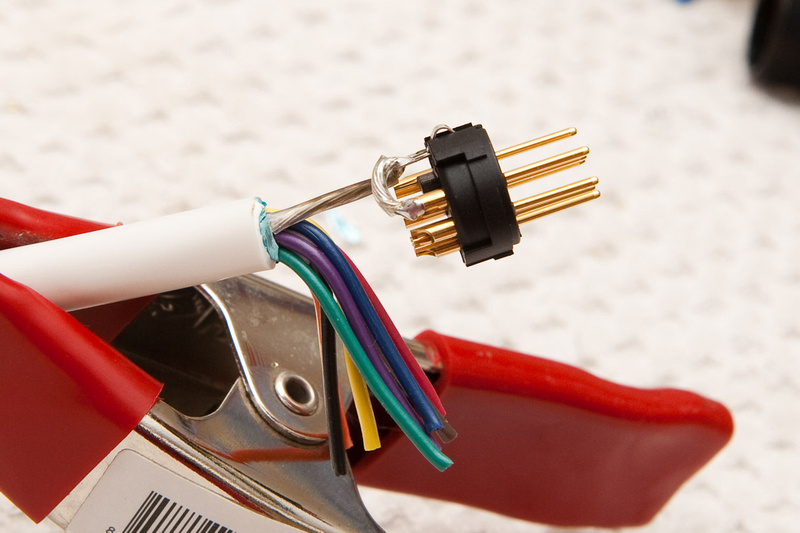
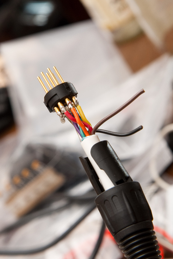
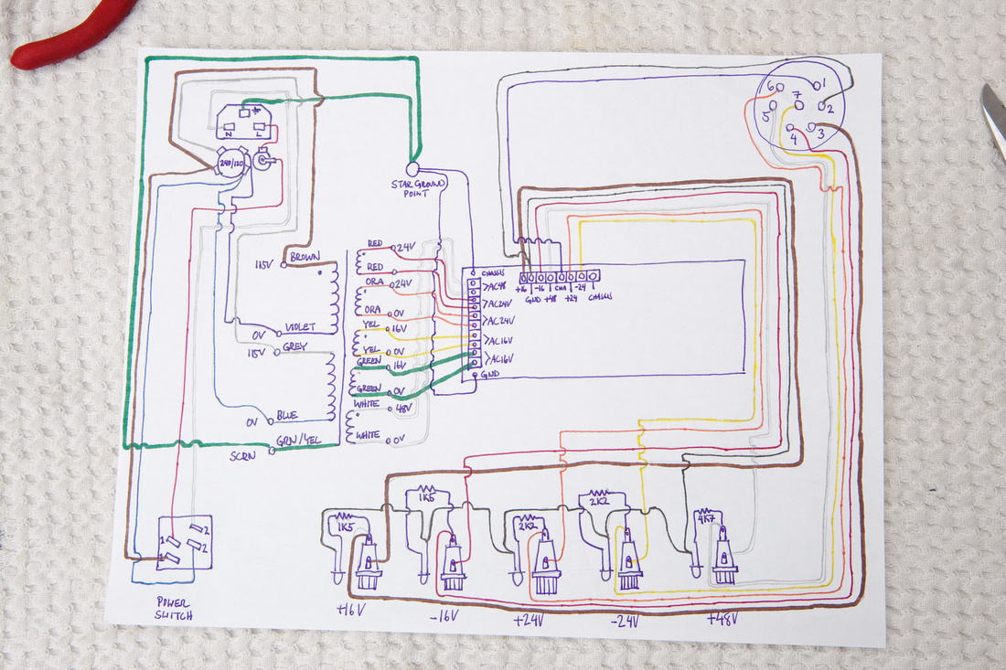
Again, referring to my map, I soldered my 7 pin Neutrik connector with the other half of the kit-provided wires that I just cut at the PCB side of the run.

p629392287-4.jpg


After evening out the cables and roughly cutting my excess off, I taped the cable ends together with the exception of the ground an chassis lead (go directly to the PCB lugs).  I then threaded the cable bundle through the rear cutout, through the cable ties towards the fuse side.

p961062429-4.jpg


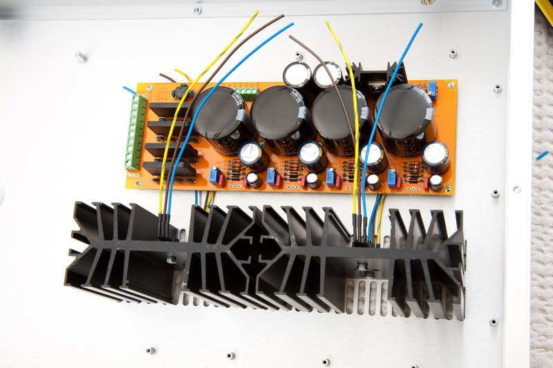
Next, I tidied up the cables and tightened down the cable ties from the neutrik connector toward the fuse side.. . then, I carefully cut and soldered the fuse output leads which also happen to connect to my LED resistors. 

p690947198-5.jpg


After this, all that's really left is to cut the leads at the PCB side, strip and tin the leads, and connect as per the map.  Note, I left a bit of slack at the Neutrik connector which made he whole internal layout not as pretty as it could have been, but knowing me, I will find a way to need to take that connector out someday, and it would be a pain trying to solder, de-solder, or otherwise tinker with that Neutrik connector after it's in the chassis without enough slack to pull it out.

p1016740960-4.jpg


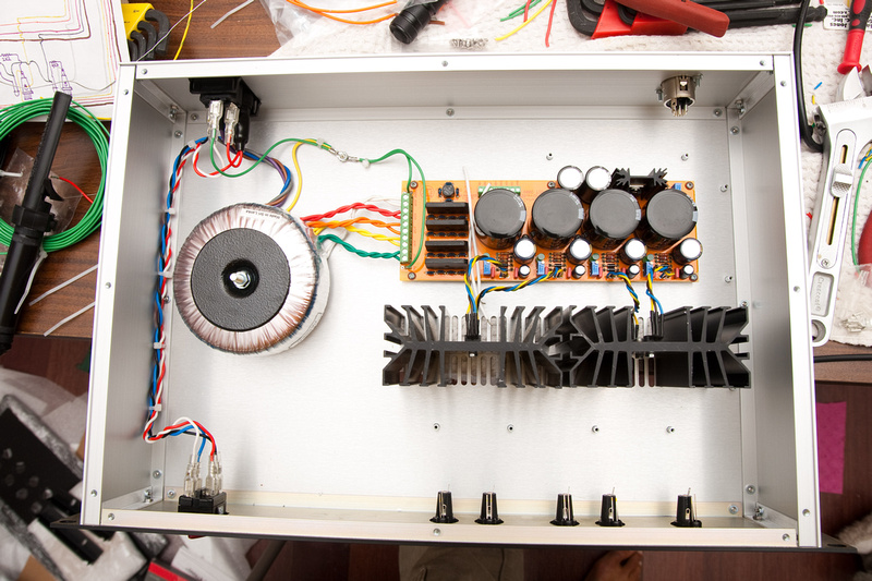
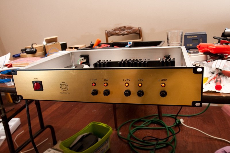
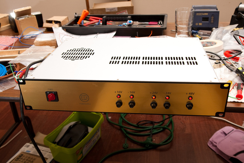
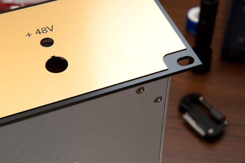
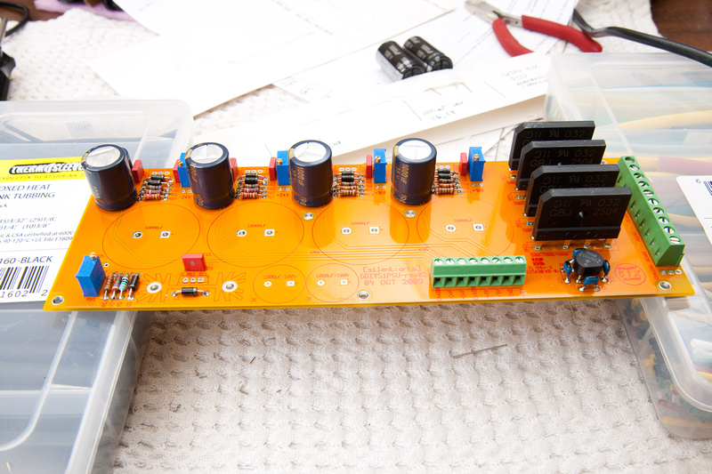
I insert the proper fuses. . . 1.6 amp for + - 16v, and + - 24v.  125mAh for 48v.
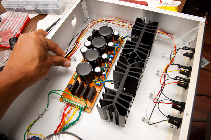
And, fire it up!

p940622594-4.jpg


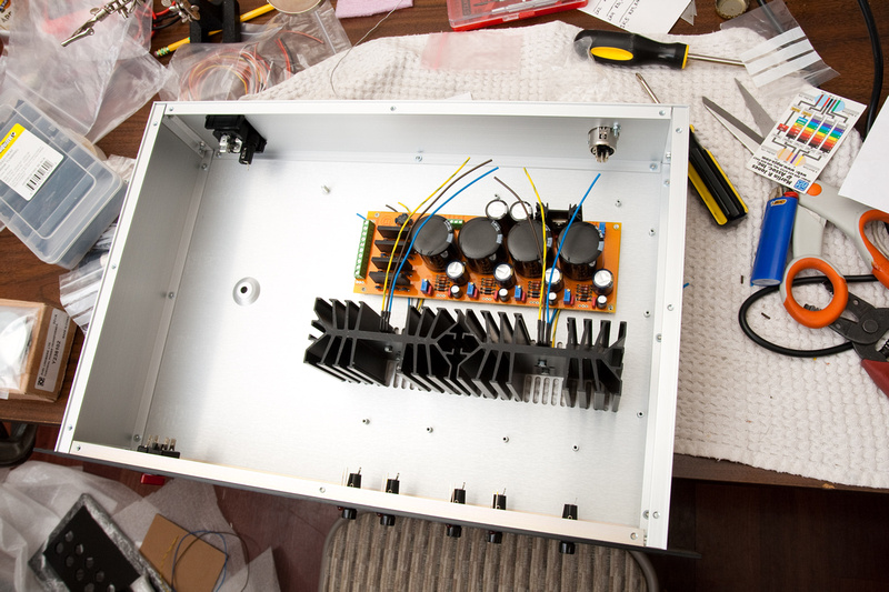
PSU complete.  What a great 1st DIY project.  I couldn't have been happier with the result and am glad to add my little contribution to the collaborative effort.  The internals I think look decent. . . there are cleaner build examples, but I did what I could and hopefully did not embarrass myself but try to set a high bar and do this project justice.

p603971788-4.jpg


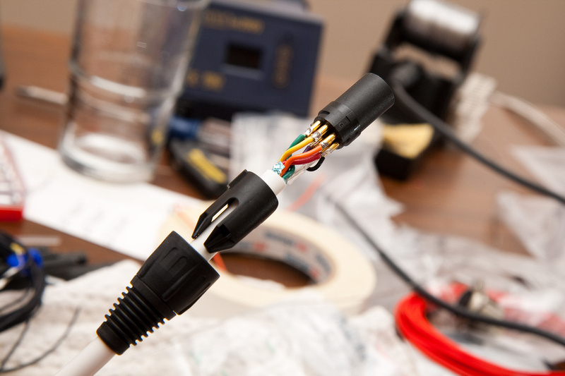
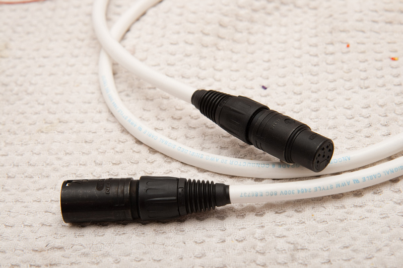
Next, I just need to make my 7 pin DC power cable, and PSU unit 1 will be online and fully operational ;D
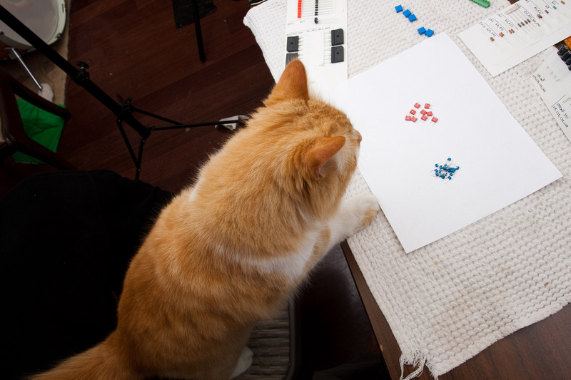
Humans win.
 
One last detail, and we should be all wrapped up here.

I'm using my 8 conductor 20 AWG shielded marine grade cable instead of the kit's because, well, you never know when you'll need to use your GDIY 51X rack in salt-water environments  ;D  Actually, it's just because I bought the stuff, and figured it couldn't hurt to have shielded cable.

I'm using the bare shield wire in the cable for "chassis" connection, and running that to the jack casing as well to complete the shield.  Might as well be thorough.

p670575032-4.jpg


And, here are the rest of the wires soldered in as neatly as I could get them:

p34063126-5.jpg


I trim off 2 excess wires from the cable because it's 8 conductor plus the shield. . . since I'm using the shield wire on pin 1, I have 2 extra.

then, same for the female side of the 7 pin connector. . .

p959510858-4.jpg


And, there it is. . . last piece of the puzzle.

p955425050-4.jpg


Now that I'm weaned off of my temporary power supply, I can get to the task of filling up this rack!
 

Latest posts

Back
Top