SSL 9K Mic Pre

GroupDIY Audio Forum

Help Support GroupDIY Audio Forum:

This site may earn a commission from merchant affiliate links, including eBay, Amazon, and others.
SaMpLeGoD said:
bruno2000 said:
Looks to me like you left out part of the clip indicator circuit.  Take a look at this.

http://www.soundskulptor.com/pdf/mp12-schematic.pdf

Bruno2000

Well, actually I didn't take that from that schematic... I think is somewhere on the net... but, yes, there's something's missing, the previous opamp an the 2 diodes and 220k resistors... well, I really what they mean with "VU in"? what the opams are doing is just like rectifying the wave... well, all I can say is mine works good, but I don't want to induce anyone in a error, if someone thinks this missing is important, please, just say it :) we're here to learn with the mistakes :p

Eddie :)

The missing opamps act as a buffer, so your audio is not driving the timing cap.
Bruno2000
 
Look like the missing 2 diodes after the missing opamps act like full wave rectifier, no?
(so this way it can detect peaks from both positive and negative sides of the sound wave)
 
keefaz said:
Look like the missing 2 diodes after the missing opamps act like full wave rectifier, no?
(so this way it can detect peaks from both positive and negative sides of the sound wave)

Yes, and the rectification is vital, but the original complaint was about the sound, and the problem was that he was directly driving the timing cap with his audio.
Bruno2000
 
bruno2000 said:
keefaz said:
Look like the missing 2 diodes after the missing opamps act like full wave rectifier, no?
(so this way it can detect peaks from both positive and negative sides of the sound wave)

Yes, and the rectification is vital, but the original complaint was about the sound, and the problem was that he was directly driving the timing cap with his audio.
Bruno2000

Maybe that's why I have that Low Pass Effect at the beginning!!!
Sorry about that!
:)

Thanks
 
The latest in my 9k adventures -
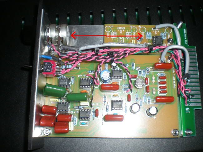
I wasn't at all happy with the pres in the little box (a couple pages back).
They sound better than ever.
The nice thing about the Lunchbox is that all the ICs work great at 16 volts.

9k5001.JPG


9k5002.JPG
 
wow I was just today wondering if edge connector, mic pre and balancing card all fit into the space available in a 500 series module - your picture answers my question :)
now I am tempted to design a little auxiliary pcb incorporating phantom power, (Single channel) balancing board and maybe clip indicator...and pad and phase switch while I'm at it.
did you notice any difference in sound/headroom with the opamps on 16V instead of 18v?
 
briomusic said:
now I am tempted to design a little auxiliary pcb incorporating phantom power, (Single channel) balancing board and maybe clip indicator...and pad and phase switch while I'm at it.
did you notice any difference in sound/headroom with the opamps on 16V instead of 18v?

I don't notice any difference at 16 volts.  Though I will say it seems there is less hiss at max gain -so maybe there's just a little less coming out of the pre at that voltage?
I wanted to add a little meter or clip light or something but decided to leave it simple.  There's not a lot of extra space - at least not with the cap I used.
 
well, since only half of the balancing board is needed, you'd have all this to play with:
9k5001space.jpg

I might have a go at it on the weekend, since I am trying to learn eagle anyway 8)
 
anyone know of knobs that fit the 4mm audio maintenance 2k2 pots for this ssl9k? having a hard time finding anything to fit.
 
Hey Tyler.
You made the same mistake as i did.
Audio Maintenance has 2 differents Dual 2k2 rev pot.
We ordered the 4mm pots....he doesnt sell many of those.
Most people buy the 1/4" shaft... ;D

Now what i did to fix this is some DIY.
i bought 2 nylon threaded standoff spacers 1/4" thick and around 1/2 long..
I took a drill bit a hair smaller than the 2k2 shaft dimension
and drilled the insides of the plastic spacer (where the threads are).
then you instert the 2k2 shaft into the hole it enters tight and voila you have a 1/4 shaft.

heres a pic of the nylon spacer i'm talking 'bout: http://media.digikey.com/photos/Keystone%20Elect%20Photos/8442E.JPG
 
Hello again!

After the success of my gssl and my passive summing mixer, i thought i would build a 9K to complement my master mix bus  ;D
And since it won't be seeing any mics I don't need phantom power / pad / phase which generally simplifies the whole thing.

I want to build a 2ch. 9K with just a power switch, two gain controls (still haven't decided if I should go for the dual gang rev-log pot or the switch), and two meters (preferably the behringer ones, will they work?). And the meter's LEDs, of course. Other changes I think of implementing is 1/4" TRS connectors instead of XLRs.

Is there something I should know before I start?

I began with getting rid of the +48V rail, since I won't need it. Is the drawing right? Or will it screw up with the +/-18V rails? Please correct me if I am wrong.
The next question I want to ask, is about the caps. Where voltages and type are specified in neeno's BOM it's OK. But what about the others? I read somewhere that it is safe to use ceramics for all pF values. But I saw some wima film caps on some finished project's. I am thinking of ordering film caps for 2.2uF, 100nF and 470nF. Would this be right? Will it make any difference?

Would there be any chance of having one pot to control both channels? (I don't think so, but I am asking just in case)

Thanks a lot for your time.

PS: How do I wire the meters. Is there anything else required? Like some small circuit that needs to be added? I don't want Keith's led-meter, the main goal is to have a simple visual of the output signal level, keep it simple, cheap and get it sound good. and get it ready fast  :'( I'm in a hurry, I have to mix an album and I want to use it! I know normally rushing isn't the best thing to do in such cases, but I will try to be as careful as I can. I need it done in 3 weeks from now  :-[
 

Attachments

  • NO48VPSU.jpg
    NO48VPSU.jpg
    61.2 KB · Views: 32
Your PSU drawing looks OK. Just leave all that stuff out and you'll have +/- 18V.

As for caps, I used all Wima caps except for some really small values where I used ceramics. Some others have done the same and I've seen others use ceramics for almost all the caps, so you could probably use whatever is easiest and it will be fine. 

Gain control, you need 2 gangs of a pot per channel. You could look for a 4-gang pot or a 4 pole switch. In your case, the switch is probably the better option since you probably want it to be exactly the same between channels.

Can't help you on the meter, but I am pretty sure they are not VU.

good luck
 
Thanks a lot mitsos! You were a lot of help.
Could I use lorlin 2pole/6position switches for 6 rough steps of gain (like the ones used on tha GSSL Attack)? I'm a little confused about the wiring too..

Anyone on the meters? Maybe I should just use 2 leds for clipping indication?? Although some needle-type meter would be far better...

PS: AS-OFF-TOPIC-AS-IT-GETS:
Mitsos, are you by any chance greek? (I'm only assuming from your nickname  ;) )
 
How about this?

http://cgi.ebay.com/New-24-step-DIY-Selector-switch-4-pole-Attenuator-Pot_W0QQitemZ110431032182QQcmdZViewItemQQptZLH_DefaultDomain_0?hash=item19b633d376&_trksid=p3286.c0.m14

Bruno2000
 

Latest posts

Back
Top