SSL 9K Mic Pre

GroupDIY Audio Forum

Help Support GroupDIY Audio Forum:

This site may earn a commission from merchant affiliate links, including eBay, Amazon, and others.
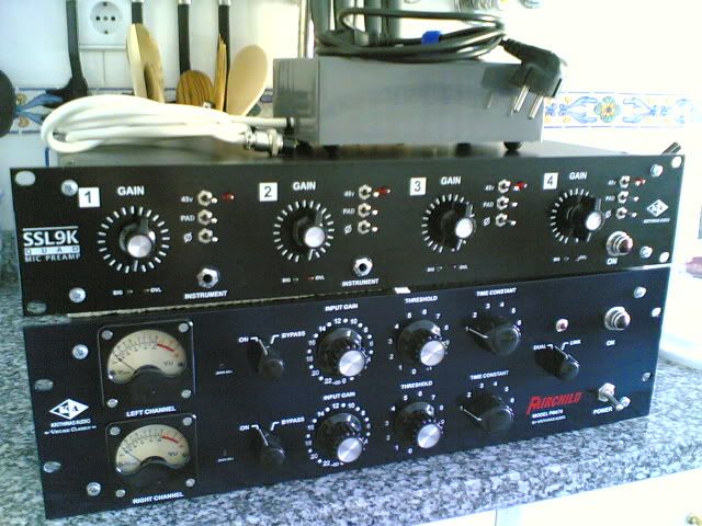
Hello I finished building one SSL9K, but there's something wrong with it.
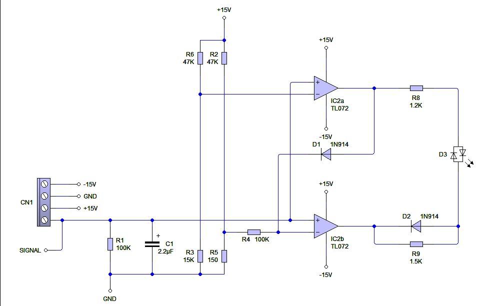
I used 24pos rotary switch to step attenuate the signal, using the Harpo's solution:

Harpo said:
maybe something like this excel file can help.

--------
edit: tidyup
I used JLM go between and DI also for the Input signal...
It sounds clear, is functioning, but...... Sounds like having a low pass filter in there, like a blanket over the sound source... very strange, what happened? I doublecheck the wiring... and it all working and seems ok...
Any Idea???

Cheers,
Eddie ;D

 
Does the pre work without the JLM DI? I'd separate the two to see if the problem is in one or the other. I think I remember someone else having a problem with the JLM on this mic pre, so maybe have a search in this thread or through the lab to see if you can find if/how the person fixed it. 
 
Hey Mitsos,

I did the search, and I found a lot of finished SSL9K with the same JLM Go Between.
I think this is not the problem... The only thing is the step atenuator I made, well, maybe the 100K resistor across the wiper and the lug are causing this... I don't know why, didn't check the schematic, I'll do it first to be sure...
Thanks a lot anyways ;)

Eddie :)
 
Hi Eddie,

test them separate as Mitsos already said.
The 100k resistor across the switch is unlikely the cause of a lpf alike effect, worst case changing a 2k5 resistor for lowest gain setting to a 2k439 one.
For lpf first thing come to mind could be a too large compensation cap.
Case this problem is DI related, knowing what is your power supply for the JLM DI, how it is powered, what dual OP-amp or the FET version you are using and what is the connected load to your supply might help to narrow this down. Maybe running out of beef. IIRC Joe once said his DI using up to 35mA each @ idle running on 48V rails.
 
Hello Harpo ;)

Well, the problem is not only with the JLM DI, through the XLR input I get the same results...
The DI is FET version, I'm using a JLM 3 Rail power supply, and it is connected in a PSU Box appart, so the rack receives already the right voltages... no toroid around the circuit... is in a box appart... really don't understand what is happening, I'll try what mitsos said.
The step attenuator is doing fine, only the sound sucks... well, let me make some tests, I'll put the results and some photos...

Cheers,

Eddie ;D
 
Hello all,

Mostly for asthetic reasons I need to add an output control to 9k.  Any suggestions on a pot and placement?  I'm thinking it should probably go before the balancer.  What 20k to 50k?

Any thoughts would be great.

Thanks.

CC
 
[quote author=isskmki]
Hi,

I've built a pair of 9k preamps and I REALLY like their sound!
Anyway, I have some hiss on both channels and I've tried practically everything to minimize it (changed almost all caps, tried replacing transistor pairs etc.) but couldn't get it lower than -52db on max gain.

The hiss level is directly affected by the gain pot. The hiss only becomes hearable on the last half of the gain pot. The level of the hiss is as follows: -95db when the pot is turned ccw, -82db when the pot is centered, -70db when the pot is at 3 o'clock and -52 when the pot is maxed. The hiss levels seems to be the same whether I have a mic connected or not.

So my question is, are these ´normal´ hiss levels on the 9K preamp ?

Thanks.

[/quote]

Re: Hum and Hiss.

Isskmki,

I had some slight hiss which only registered on the meter when the volume was at full gain. Plugging in a mic made the hiss go away.

Kato
 
Hello Everybody,

Just finished another project, the QUAD SSL9K (4x SSL9K) on a box!
I made the PSU outside the box, with a 50VA 18-0-18 Toroid and JLM 3 rail AC/DC kit!
All the 4 channels have JLM Go between, and the first two have the JLM FET DI also. The Gain are made with 24 Step Rotary Switches! work great and the output board is balanced with THAT 1646!
I fit a signal / peak indicator for each channel, but I have a question:

      - Where do I have to drain the signal to be analyzed?

I tried at the out of the go-between, but it just ruin the signal, act like a low pass-filter... the sound became muddy! so, I'm bleeding the signal at the XLR's out pin 2. I know doing that, I'm just monitoring the output,not the input that was my goal... but doing that the signal stays intact! I'll leave here the signal peak indicator I used and some bad mobile phone photos :-\ sorry about that!
Just two previous answers, yes, is in my kitchen, and yes above is my PM670 waiting for lolo-M SCamp board :p

Cheers,

Eddie  ;D

the horrible photos:

QUADSSL9K.jpg


SSL9KChannel1.jpg


I used 2 leds (green and red) instead a single 2 color one for the clipping indicator
ClippingIndicator.jpg


Attachments

  • QUAD SSL9K.jpg
    QUAD SSL9K.jpg
    157.5 KB · Views: 137
SaMpLeGoD said:
I'm just monitoring the output,not the input that was my goal...
Just curious, why do you want a clip indicator on input, I mean if you monitor before preamp circuit, you won't have a visual clip indication if it's clipping on later stage with a gain pot setting too much CW
 
I'm not 100% sure, but I would take the signal between the preamp and balance board. Did you try that? Just remember that you have an extra 6dB gain from the THAT chip.

Also, how did you solve your past sound issues? Was it because of where you were putting the clip indicator?

Thanks for posting the clip schemo. Did you put the two LEDs in antiparallel?
 
Looks great-
how did you print the white on the black panel?

By chance has anyone tried stuffing a 9k in to a 500-series box yet?  I'm considering it.  I figure with one of those Pico-500-edge card connectors and a bracket like owel was selling it shouldn't be too hard.  Any opinions?
 
Just curious, why do you want a clip indicator on input, I mean if you monitor before preamp circuit, you won't have a visual clip indication if it's clipping on later stage with a gain pot setting too much CW

Well, what I really wanted is a visual indicator that something is going in! I actually feel comfortable with it when I'm routing the stuff. So, I start to think, if I'll do that why can't I monitoring and see if I'm overloading the preamp at the input?... ok not a Mic will do that, but like recording a Keyboard via DI input or even some kind of pre-amped stuff, direct guitar modules... they usually are plenty of output! so why not? I know that I can easily read that at the output, but, whatever... it's done :) and it works  ;D


mitsos said:
I'm not 100% sure, but I would take the signal between the preamp and balance board. Did you try that? Just remember that you have an extra 6dB gain from the THAT chip.

Also, how did you solve your past sound issues? Was it because of where you were putting the clip indicator?

Thanks for posting the clip schemo. Did you put the two LEDs in antiparallel?

Yeah, I really forgot that the THAT Chip boosts +6dB... I think is a good place indeed!
About my sound issues... that was the problem, at the time I already have the clipping indicator, but I was bleeding it from the out of the JLM Go-Between... I don't know why has some low pass effect, maybe an impedance problem...

Talking about the PSU... I measured each preamp and it drain around of 174mA, around 300mA at almost full gain.
The JLM PSU (3 rail) delivers 1.5A each +/- rail maximum, but only 300mA for the 48V rail... is that sufficient if I'm planing like supply 4 condenser mics at the same time? My toroidal is ok, and it delivers 1.35A each secondary (50VA). I actually substitute the 12V lamp I had on the jewel light support for a Ultra Bright 5mm led that has only 20mA of consumption... the lamp was consuming 150mA! that's crazy!

Cheers,

Eddie  ;D
Just to be sure!
 
geoff004 said:
Looks great-
how did you print the white on the black panel?

By chance has anyone tried stuffing a 9k in to a 500-series box yet?  I'm considering it.  I figure with one of those Pico-500-edge card connectors and a bracket like owel was selling it shouldn't be too hard.  Any opinions?

It was printed in a serigraphy's facility! I did all the sketches on photoshop... and the rest are with them! made all the holes, and start stuffing!

About stuffing a 9k in to a 500-series box, it is a nice idea! I think you could manage that easily, the only issue is the contacts, they need to be made separately... the rest are connections!

Eddie :)
 
btw, serigraphy is more commonly called silkscreening

thanks again for the tl072 schemo. RE: 48V current, I read somewhere that mics are supposed to be designed to use 10mA max. Manufacturers may or may not follow that, but I would think you'd be fine with 20-25 mA per channel and you've got 75.  good job on the preamp... post some inside pics if you can, always nice to see.
 
mitsos said:
btw, serigraphy is more commonly called silkscreening

thanks again for the tl072 schemo. RE: 48V current, I read somewhere that mics are supposed to be designed to use 10mA max. Manufacturers may or may not follow that, but I would think you'd be fine with 20-25 mA per channel and you've got 75.  good job on the preamp... post some inside pics if you can, always nice to see.

Ok, silkscreening! :)
If you want I can post the board I made for that... no problem!
Cheers

Eddie :)
 
mitsos said:
thanks again for the tl072 schemo.

I'll share in case of someone need, my board's drawings for one of them... in the SSL9K I made 4 of them, just linked to share the voltage rails.
You can choose between one led with two colors, or two different leds in opposition, both cases it will work!
Just download the zip file in this SendSpace link below, it contains: the board (cooper side), the top view (parts placement) and BOM.
The board is 57mm x 29mm (nevermind the BOM I wrote 5.7mm and 2.9mm by mistake) sorry about that!

Here is the Zip file with the Clipping Indicator stuff

Hope it helps!

Cheers,

Eddie  ;D
 
Looks to me like you left out part of the clip indicator circuit.  Take a look at this.

http://www.soundskulptor.com/pdf/mp12-schematic.pdf

Bruno2000
 
bruno2000 said:
Looks to me like you left out part of the clip indicator circuit.  Take a look at this.

http://www.soundskulptor.com/pdf/mp12-schematic.pdf

Bruno2000

Well, actually I didn't take that from that schematic... I think is somewhere on the net... but, yes, there's something's missing, the previous opamp an the 2 diodes and 220k resistors... well, I really what they mean with "VU in"? what the opams are doing is just like rectifying the wave... well, all I can say is mine works good, but I don't want to induce anyone in a error, if someone thinks this missing is important, please, just say it :) we're here to learn with the mistakes :p

Eddie :)
 

Latest posts

Back
Top