Silvas
Well-known member
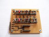
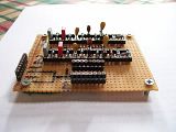
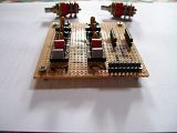
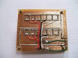
My sidechain proto board....waiting to be installed.


Kingston said:Great idea with proto board!
Looks like I need to do something like that as well.
I'm currently fighting with Lundahl LL1676 input and output transformers (sidechain will stay as edcors). The Lundahls sound quite brilliant but I screwed up something while installing a custom PCB I had designed for them. Compression sounds really odd. Probably something quite simple.
Silvas said:Are you going to do MS matrix with them?
which is like it should beFreddy G said:The voltages don't change in mine with or without amp boards connected
[silent:arts] said:which is like it should beFreddy G said:The voltages don't change in mine with or without amp boards connected
(except stock heater part of the PSU)
skal1 said:my dc voltage at R1 junction of D4 and Q4 pin 2 is 414vdc is this right is it on the high side
kazper said:Airbrush ? Paint brush and steady hands?
Enter your email address to join:
