[silent:arts]
Well-known member
thanks Kingston, I nearly missed that beauty 


phishman13 said:Not sure if this has been definitively answered in the many pages of this post, but these ceramic tube sockets from tubedepot.com fit these boards perfectly:
http://www.tubedepot.com/sk-9pinpcf.html
Just an fyi.
mitsos said:I'm not 100% sure of the resistor values for the switches, but I guess the values Kingston posted should work fine? Is that what most people are using?

mitsos said:So, they're supposed to be 15K, right? So basically you're saying build two of the same switch, right?
mitsos said:From what I can see, that's how the fairchild does it right?
I was thinking about the pot thing.. You might be able to get away with getting a custom pot from Omeg (they might even let you sample). If they won't do 15K, you could get a custom 4Gang 10K,4K7,10K,4K7, and use one 10K and one 4K7 in series for each 15K. Would be a slightly pricey pot in small quantities, but (without looking at the schemo) I think it would work.Kingston said:Next time I will shortcut with a 15-20k log dual pot if I manage to find such a thing. Actually for gain control you could just use a 600 ohm T-attenuator before the input transformer, just like with 1176 for example. Might actually be a stellar idea with the hairball version. Then just wire CV directly to input transformer secondary center tap.
Kingston said:I used this calculator: http://homepages.tcp.co.uk/~nroberts/atten.html
emrr said:Someone needs to report on any differences with the CT of the sec tied to ground with the center of the pot/CV tie point, versus the stock condition.
Bluebird] I removed the input attenuator and hooked the input transformer secondary right up to the grids of the 6BA6's. I attached the CV voltage to the center tap of the input transformer like on the original 660. I used a 600 ohm T attenuator in front of the input transformer. It sounds better to me now...[/quote] But honestly I don't know [i]how [/i]it could actually sound any better. The more important factor is the time/pain saved when using a high quality 600 t-attenuator vs. some 24-step manually tinkered rotary switch. [quote author=[silent:arts] said:while prototyping I used a 10K pot in series with a 4K7 resistor.
worked fine.
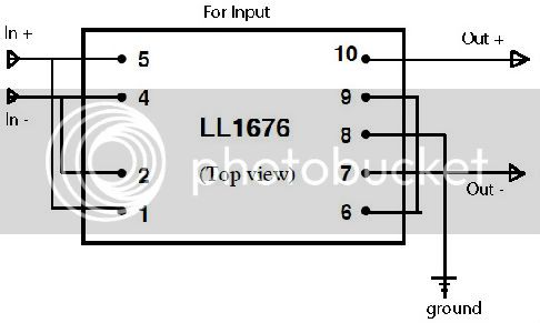
rrs said:would this be how to wire for the poorman input.
Enter your email address to join: