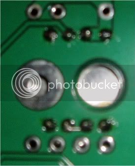
Pins 2 and 3 on the input transformer?rrs said:...The bridge between pin 2 and 3 seemed to be shorting to ground....
You are using an out of date browser. It may not display this or other websites correctly.
You should upgrade or use an alternative browser.
You should upgrade or use an alternative browser.
API 312 Thread!
- Thread starter fallout
- Start date


Help Support GroupDIY Audio Forum:
This site may earn a commission from merchant affiliate
links, including eBay, Amazon, and others.
rrs
Well-known member
Well maybe 5 and 6 I cant remember how there numbered but the two pins that are bridged in the photo.
bobschwenkler
Well-known member
Well, you do need to have some pins of the primaries connected in some way. This connects the high and low conductors of your differential signal, and you will not get any signal passing if they're not. Did you run audio through it? If you just tested the +48, that may have opened your short, but now the audio should not.
Check with your meter for shorts from the transformer primary pins to audio ground and see if that gives you anything. You should not have any continuity between these parts of the circuit..
Check with your meter for shorts from the transformer primary pins to audio ground and see if that gives you anything. You should not have any continuity between these parts of the circuit..
rrs
Well-known member
I have audio and 48V now working.
There was continuity from Ground pin to primary pins (the ones connected together). I removed the conection the resolderd the same connection and now there is no continuity between these pins and ground. Maybe the bridge was too cloce to the PCB????
All seems perfect now.")
There was continuity from Ground pin to primary pins (the ones connected together). I removed the conection the resolderd the same connection and now there is no continuity between these pins and ground. Maybe the bridge was too cloce to the PCB????
All seems perfect now.
bobschwenkler
Well-known member
Ok, cool. Glad you got it solved.
Rybow
Well-known member
Hey! I was looking to build a couple of these, but I can't seem to find the link in the White Market to the PCB's for the rack mount version. Are they still available somewhere? Thanks.
bobschwenkler
Well-known member
Insomniaclown said:Hey! I was looking to build a couple of these, but I can't seem to find the link in the White Market to the PCB's for the rack mount version. Are they still available somewhere? Thanks.
There's a link to the page with info and to buy in my signature. And I'm not sure what you mean by the rack mount version, but the PCBs can be mounted any way one wants to.
Rybow
Well-known member
bobschwenkler said:Insomniaclown said:Hey! I was looking to build a couple of these, but I can't seem to find the link in the White Market to the PCB's for the rack mount version. Are they still available somewhere? Thanks.
There's a link to the page with info and to buy in my signature. And I'm not sure what you mean by the rack mount version, but the PCBs can be mounted any way one wants to.
Hey Bob. Thanks for the reply. I got a little worried for a second.
By the rackmount version, I was meaning your board. Sorry about that. The only PCB's I could find were for the 500 series format.
Thanks again!
bobschwenkler
Well-known member
Sure thing.Insomniaclown said:bobschwenkler said:Insomniaclown said:Hey! I was looking to build a couple of these, but I can't seem to find the link in the White Market to the PCB's for the rack mount version. Are they still available somewhere? Thanks.
There's a link to the page with info and to buy in my signature. And I'm not sure what you mean by the rack mount version, but the PCBs can be mounted any way one wants to.
Hey Bob. Thanks for the reply. I got a little worried for a second.
By the rackmount version, I was meaning your board. Sorry about that. The only PCB's I could find were for the 500 series format.
Thanks again!
Rybow
Well-known member
Alright. So I am planning out my 312 project, and I just want to run the plan by you cats before I start ordering parts. I have decided to just do a single channel DI style mic pre for now. Here is the plan:
Power supply- 15VA 2 x 18v toroid, SSL 9K PCB from Gustav.
gar2520 opamp kit
CM75101APC input transformer, EA 2503 output transformer
API PCB from Mr Schwenkler
Daking mic pre one style enclosure. Hammond has some stuff, but is there any other supplier of this type of thing?
I really want to add a DI input, but no idea on whats needed. If someone could point me in the right direction, that would be very cool. This will be my first DIY mic pre, and my first API style mic pre, so I look forward to the results. What a freakin sweet project!
Bo Hansen's DI mod for going straight into the DOA on a 312 is hard to beat...and simple. Do a search and you will find the link. Not real familiar with Bob's layout but I'm sure it could be made to work.
janczmok
Well-known member
I've got two Reliquia 312 v3.1 here (nearly full assembled) and have some questions:
1)On the Output Transformer Cutout in die PDF, i see a small design with the Hi-Z, but that is missing on my PCB; i assume this is the HI_Z Mod. I can apply this without the PCB, but need to know if that's needed for the v3.1 version.
2)It may sound stupid, but if i use the APP2055 in the OP1 Setup, do i need to solder U1 ? Or is this "alternative" ?
3)Supply Voltage: What voltages do i need on the 312's ? ( i don't have the 312PSU here, but some other PSU options ... )
thanks so far
bobschwenkler
Well-known member
The Hi-Z input sub boards I thought normally shipped with the 312 board. At least mine I built did. It's not necessary for the circuit. If you installed a relay for the Hi-Z switching I'd assume that the NC connection is given to the input transformer, but I could be wrong there. If this is the case, you might be best off desoldering the relay and just installing jumpers here.
I'm not totally sure what you're asking with question 2. Fabio's schematic doesn't have BOM numbers for the opamps. Are you talking about the op amp that's used for the preamp gain? What is the OP1 setup?
Supply voltages depend on the op amp you're using. If it's a 2520 they're generally given +/-16 or 17 volts.
janczmok
Well-known member
Given the switches in front of you, you have a total of 3 "external" boxes on the PCB
- one being OP1 (mine being a APP2055) ,
- one being TF3 (mine A262A3C)
- one being TF2 (output transformer)
i'm not sure about yet if i want to use the HI_Z, but i can probably build my own "small" PCB for it.
regarding the U1 am seeing it in the R312sch_rev3-1.pdf file under "Options". My reading would mean "either" use the U1 or the other, but i am not sure, as i haven't built a 312 before.
mitsos
Well-known member
- Joined
- May 4, 2007
- Messages
- 2,886
Exactly. U1 is an IC opamp alternative to a DOA.janvanvolt said:regarding the U1 am seeing it in the R312sch_rev3-1.pdf file under "Options". My reading would mean "either" use the U1 or the other
Also, if using the OEP input, your zobel network will be different from Fabio's schematic. I think there are some possible values in this thread somewhere.
You will also need a 4th power rail if using relays.
good luck with it. Should turn out nice when done.
janvanvolt said:I've got two Reliquia 312 v3.1 here (nearly full assembled) and have some questions:
2)It may sound stupid, but if i use the APP2055 in the OP1 Setup, do i need to solder U1 ? Or is this "alternative" ?
don't solder U1 , there is the APP2055 in place of it.
Pier Paolo
janvanvolt said:I've got two Reliquia 312 v3.1 here (nearly full assembled) and have some questions:
3)Supply Voltage: What voltages do i need on the 312's ? ( i don't have the 312PSU here, but some other PSU options ... )
thanks so far
you can use the APP2055 with +/-24V of supply power.
With this supply voltages you can have 32 dBu out using an APP2055.
Pier Paolo
I have seen the Fabio's 312 so I've replaisd two of your questions but I need the schematic of your preamp version so I can help you better.janvanvolt said:Given the switches in front of you, you have a total of 3 "external" boxes on the PCB
- one being OP1 (mine being a APP2055) ,
- one being TF3 (mine A262A3C)
- one being TF2 (output transformer)
i'm not sure about yet if i want to use the HI_Z, but i can probably build my own "small" PCB for it.
regarding the U1 am seeing it in the R312sch_rev3-1.pdf file under "Options". My reading would mean "either" use the U1 or the other, but i am not sure, as i haven't built a 312 before.
I have seen R312sch_rev3.pdf
the APP2055 can be used with the hi-zi input.
Moreover, using an APP2055, that's an ultra low noise DOA , the 312 works very quiet, moreover,
for the hi-zi input it's possible having a strong low noise factor.
Pier Paolo
the APP2055 can be used with the hi-zi input.
Moreover, using an APP2055, that's an ultra low noise DOA , the 312 works very quiet, moreover,
for the hi-zi input it's possible having a strong low noise factor.
Pier Paolo
janczmok
Well-known member
Hi, i mailed you my documentation.
(and thanks for the Hi-Z info. Can't await to get the missing transformator and power it up
(and thanks for the Hi-Z info. Can't await to get the missing transformator and power it up